Dual mode sensing for vibratory gyroscope

a vibratory gyroscope and sensing technology, applied in the field of vibratory gyroscopes, can solve the problems of adversely affecting the sensing capability of the gyroscope, high mechanical noise,

Active Publication Date: 2011-09-20
INVENSENSE
View PDF191 Cites 41 Cited by
  • Summary
  • Abstract
  • Description
  • Claims
  • Application Information

AI Technical Summary

Problems solved by technology

Accordingly, a problem with conventional systems is that they may not be sensitive enough in some applications and may also produce a high amount of mechanical noise to adversely affect the sensing capability of the gyroscope.

Method used


Image

  • Dual mode sensing for vibratory gyroscope
  • Dual mode sensing for vibratory gyroscope
  • Dual mode sensing for vibratory gyroscope

Examples


Embodiment Construction

[0014]The present invention relates generally to a drive and sense subsystems formed within a device layer, and a substrate. The following description is presented to enable one of ordinary skill in the art to make and use the invention and is provided in the context of a patent application and its requirements. Various modifications to the preferred embodiment and the generic principles and features described herein will be readily apparent to those skilled in the art. Thus, the present invention is not intended to be limited to the embodiment shown but is to be accorded the widest scope consistent with the principles and features described herein.

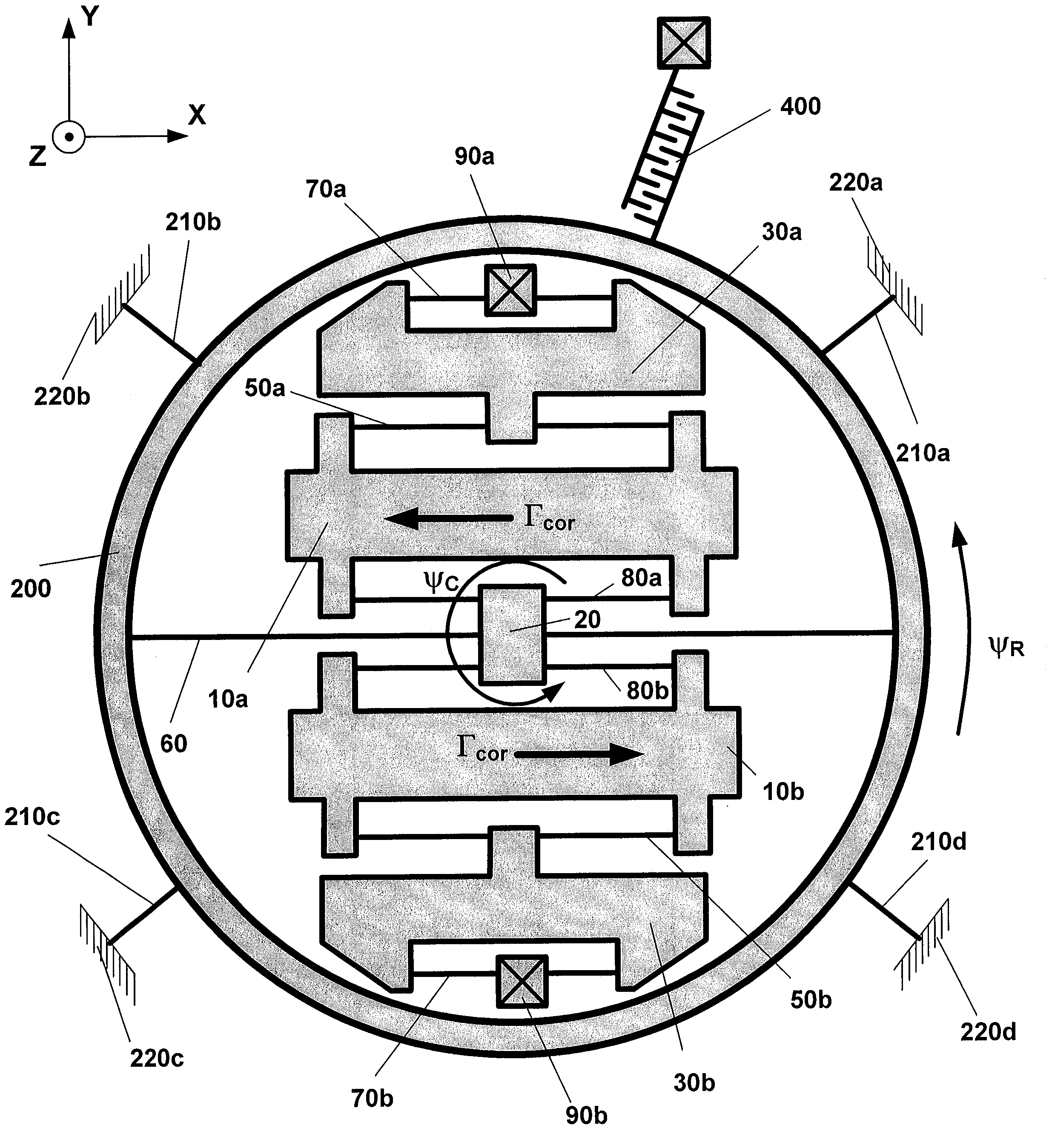
General Structure of the Angular Rate Sensor

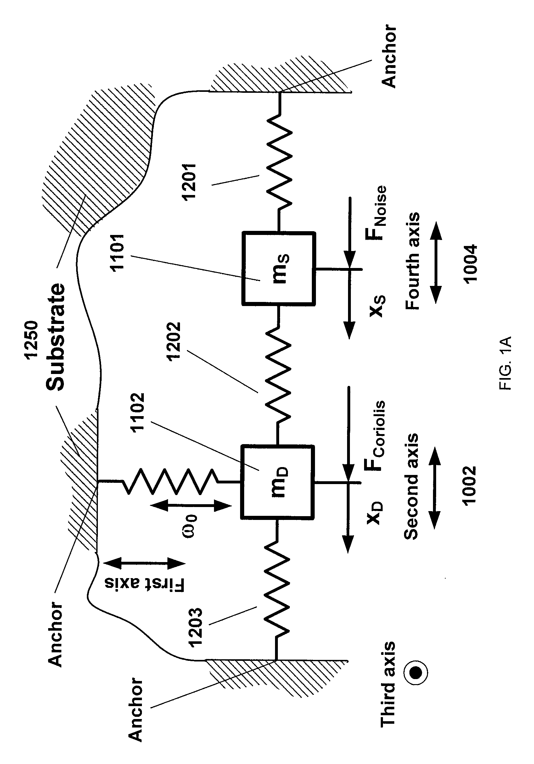
[0015]Referring to the FIG. 1A, the angular rate sensor comprises drive and sense subsystems, and a substrate. The drive and sense subsystems 1002 and 1004 respectively are supported by the substrate 1250 through anchor points, and the drive and sense subsystems 1002 and 1004 are flexibly couple...


PUM


Abstract

An angular rate sensor is disclosed. The angular rate sensor comprises a substrate and a drive subsystem partially supported by a substrate. The drive subsystem includes at least one spring, at least one anchor, and at least one mass; the at least one mass of the drive subsystem is oscillated by at least one actuator along a first axis. Coriolis force acts on moving the drive subsystem along or around a second axis in response to angular velocity of the substrate around the third axis. The angular rate sensor also includes a sense subsystem partially supported by a substrate. The sense subsystem includes at least one spring, at least one anchor, and at least one mass.

Description

FIELD OF THE INVENTION[0001]The present invention relates to a vibratory gyroscope and more particularly to a drive and sense subsystems formed within such a gyroscope.BACKGROUND OF THE INVENTION[0002]In vibratory gyroscopes with two sense peak structures, conventional designs require sense masses to be split in order to achieve two mode dynamics [Acar et al., U.S. Pat. No. 6,845,669]. Additionally, in conventional systems in the two sense peak design, the sense masses are never anchored [Acar et al., U.S. Pat. No. 6,845,669]. Accordingly, a problem with conventional systems is that they may not be sensitive enough in some applications and may also produce a high amount of mechanical noise to adversely affect the sensing capability of the gyroscope.[0003]Accordingly what is needed is a vibrating gyroscope and a system that overcomes these issues. The present invention addresses such a need.SUMMARY OF THE INVENTION[0004]An angular rate sensor is disclosed. The angular rate sensor com...

Claims


Application Information

Patent Timeline
Patent Type & Authority Patents(United States)
IPC IPC(8): G01P9/04G01C19/56
CPCG01C19/5719
Inventor SEEGER, JOSEPH
Owner INVENSENSE
Why Eureka
Try Eureka