Bag of a heat-shrinkable gas-barrier thermoplastic film

a thermoplastic film and gas barrier technology, applied in the field of bags of heat shrinkable gas barriers and thermoplastic films, can solve the problems of reducing the commercial value of the contents, difficult to tear the package, and conventional methods have their own limitations, so as to minimise excess material, minimise excess material, and minimise excess material.

Active Publication Date: 2011-09-20
CRYOVAC ILLC
View PDF31 Cites 14 Cited by
  • Summary
  • Abstract
  • Description
  • Claims
  • Application Information

AI Technical Summary

Benefits of technology

[0032]By the present invention, the manually graspable tab may be formed in a bottom corner of the bag, which in a bag with a bottom edge that extends perpendicularly along substantially its entire length to the first and second side edges is often otherwise excess material. This permits the parts of the first and second seals other than in that corner to be formed very close to the bottom edge, thereby minimising the material of the bag that does not form part of the area for receiving the at least one item. Additionally, since the space between the first and second seals is closed, any air or other gas contained in the space when the seals are formed will be compressed during heat shrinking and may thereby reduce the amount of heat shrink of the film material between the seals, particularly of the manually graspable tab.
[0038]The shaped portion of the second seal may be generally U- or V-shaped. The height of the shaped portion of the second seal at the apex is partly a function of the minimum size of the tab desirable after shrinking the bag. It is also a function of the desire to minimise excess material in the bag, and in one embodiment of the unshrunk bag the height of the shaped portion of the second seal at the apex is in the range of about 30 to 80 mm from the bottom edge, advantageously in the range of about 40 to 60 mm. The first seal should extend around or past the shaped portion as close as possible to the apex, also to minimise excess material in the bag, with the minimum spacing being defined by the ability to keep the first and second seals separate. In one embodiment of the unshrunk bag, that minimum spacing is no more than about 5 mm, for example about 3 to 4 mm.
[0039]The spacing of the shaped portion from said one of the first and second side edges is also a function of the minimum post-shrink tab size and the desire to minimise excess material. Preferably, that spacing in the unshrunk bag is no more than about 120 mm, for example in the range of about 30 to 100 mm, most preferably in the range of about 30 to 50 mm.

Problems solved by technology

On the other hand, packages overwrapped in heat-shrinking film have the disadvantage that the film sticks so closely to the underlying surfaces and are in such tension that they are difficult to tear when the package must be opened.
However, these conventional methods have their own limitations.
In the first approach, if the perforations overlie the contents of the package the perforations will grow in size upon heat treatment of the heat shrinkable film so that contaminants can potentially get into the package through the holes, thereby reducing the commercial value of the contents.
In some cases, the perforations may rupture during handling.
The second approach needs a special apparatus for making the U-shaped hole and, furthermore, the use of paper seals adds to the production cost.
In any event, these two methods are not suited to vacuum packages, since an opening in a portion of the bag overlying the packaged item or items will lead to leakage of the vacuum.
The third approach has the inherent disadvantage of being cumbersome.
A problem with this arrangement is that the tab shrinks at the same rate as the remainder of the bag when the film is shrunk around the contents, for example by at least 50%, and may therefore require a large portion of the pre-shrunk film material or be too small to readily grasp after shrinking
This system has the disadvantage that, when shrunk, the protruding tongue may not be visible or may have an unpleasant appearance and may be difficult to grip.
A problem with the proposals in these U.S. patents is the substantial volume of film material that is taken up by the tear tab, and the associated cost.

Method used


Image

  • Bag of a heat-shrinkable gas-barrier thermoplastic film
  • Bag of a heat-shrinkable gas-barrier thermoplastic film
  • Bag of a heat-shrinkable gas-barrier thermoplastic film

Examples


Embodiment Construction

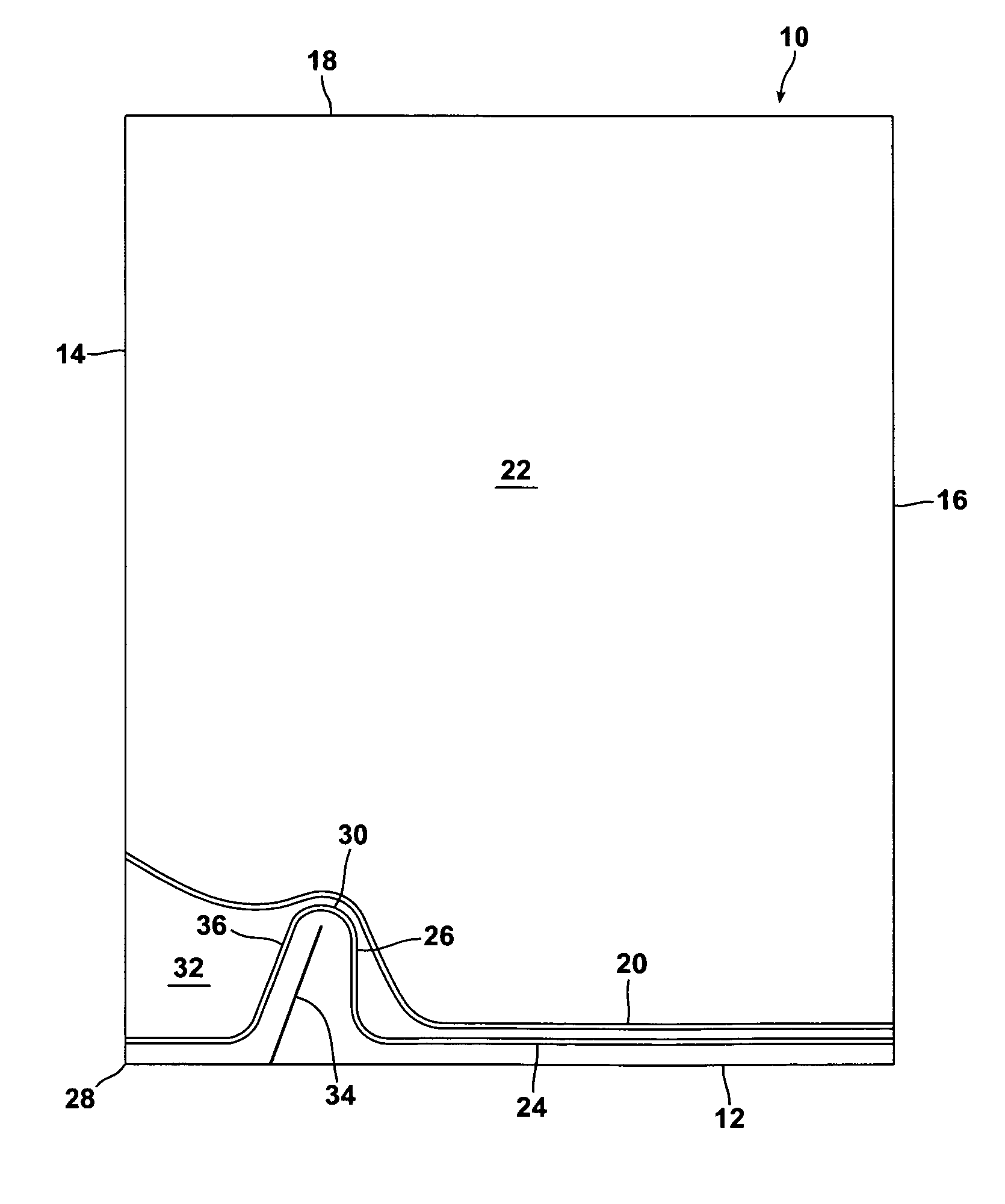
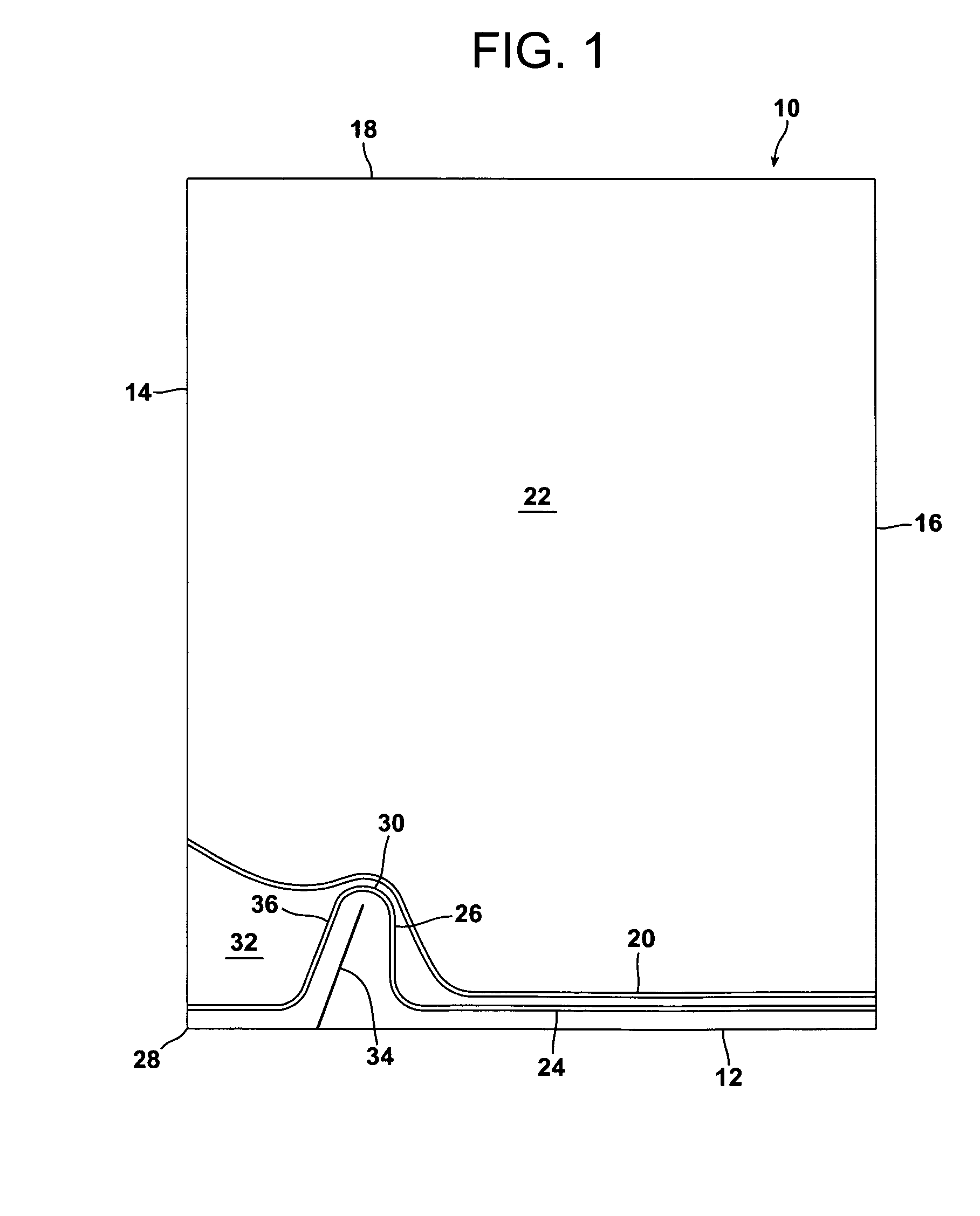
[0046]Referring to FIG. 1, a bag 10 of a heat shrinkable gas-barrier, thermoplastic film for packaging one or a plurality of items is provided, the bag comprising a bottom edge 12, two side edges 14 and 16 and an open mouth 18 for the introduction of the item or items to be packaged between opposed film portions.

[0047]The bottom of the bag is closed by a first heat seal 20 adjacent the bottom edge 12 connecting the two side edges 14 and 16. The first seal 20 defines with the open mouth 18 and the side edges 14 and 16 an area 22 of the bag for receiving the item or items to be packaged via the open mouth.

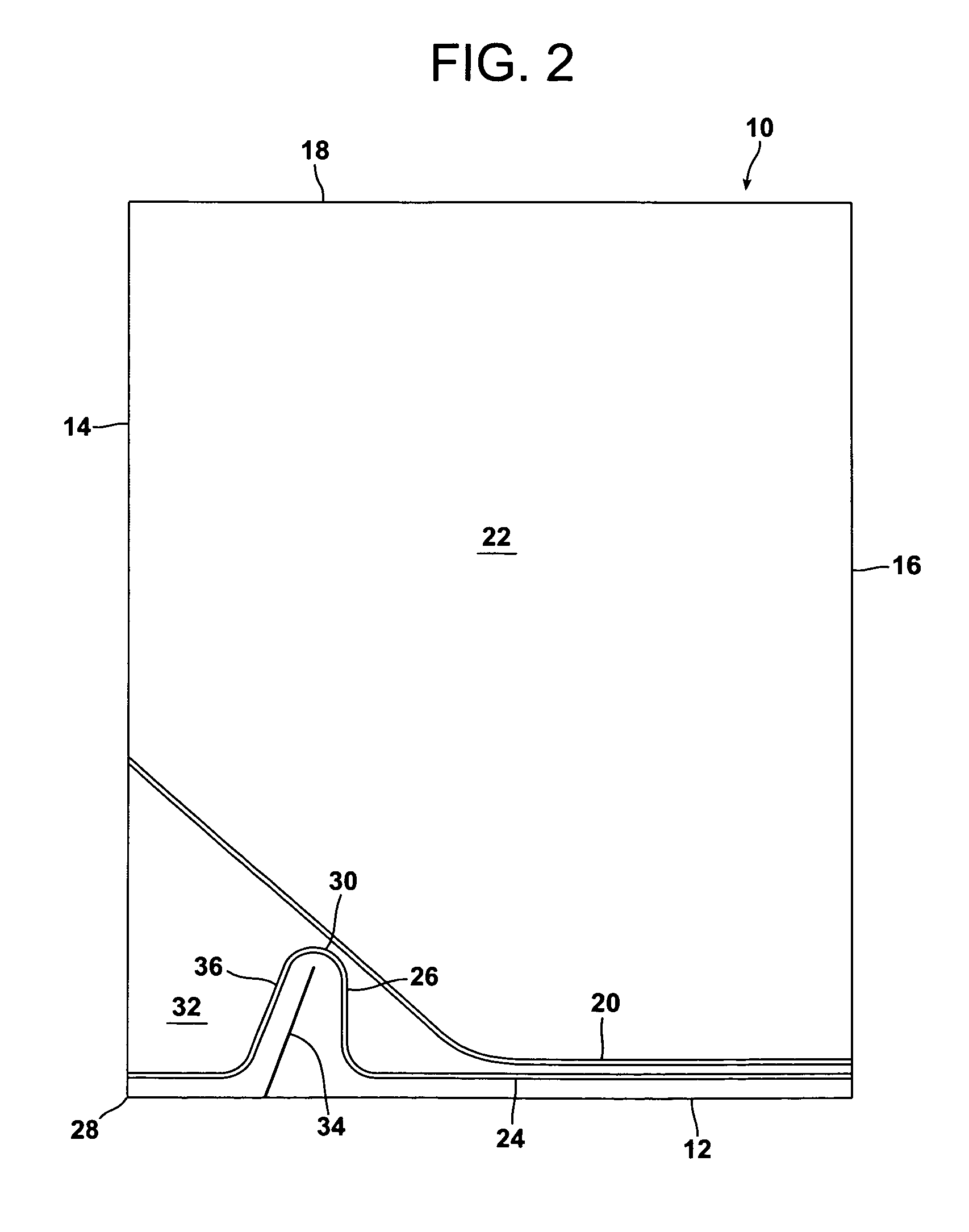
[0048]A second heat seal 24 connects the side edges 14 and 16 between the bottom edge 12 and the first seal 20. The majority of the second seal 24 extends at least substantially parallel to the bottom edge 12, but the second seal has a shaped portion 26 adjacent a corner 28 of the bag defined by the bottom edge 12 and the side edge 14. The shaped portion 26 projects towards the open ...


PUM

PropertyMeasurementUnit
distanceaaaaaaaaaa
heightaaaaaaaaaa
distanceaaaaaaaaaa

Abstract

A bag of a heat shrinkable, gas-barrier thermoplastic film for packaging an item comprises a first seal adjacent a bottom edge and connecting first and second side edges, and defining an area between it, the side edges and a top edge for receiving the item, a second seal along the bottom edge or between the bottom edge and the first seal and connecting the side edges, and having a shaped portion adjacent a corner of the bag at the first side edge and the bottom edge which projects towards the top edge, and a precut extending from the bottom edge towards an apex of the shaped portion, the first seal extending from the second side edge towards the shaped portion at a level below the apex and around the shaped portion to the first side edge, and a manually graspable tab being formed between the first side edge, the first and second seals adjacent the first side edge and the shaped portion.

Description

TECHNICAL FIELD[0001]The invention relates to a bag of a heat shrinkable gas-barrier, thermoplastic film for packaging one or a plurality of items and to a package comprising the bag and one or more items sealed in the bag.[0002]The invention particularly relates to an easy openable bag for vacuum shrink packaging. The bag may be made from seamless tubular film or flat film that is folded and joined, for example at one side to form a side seal. Alternatively, it may be in the form of a pouch formed from two separate pieces of film that are joined together with side seals.BACKGROUND ART[0003]One of the packaging methods that is in common practice today is vacuum shrink packaging, according to which an article of interest is wrapped with a heat-shrinkable thermoplastic film in the form of a bag and the package is vacuumised, heat sealed and cut off along the edge portions. The obtained package is heat shrunk to provide a tight appearance. Heat shrink packaging has gained increased pop...

Claims


Application Information

Patent Timeline
Patent Type & Authority Patents(United States)
IPC IPC(8): B65D33/00
CPCB65D81/2023B65D75/5816
Inventor SMITH, ADRIAN MAXWELL WILLIAM
Owner CRYOVAC ILLC
Why Eureka
Try Eureka