Rotary receptacle assembly
a rotary receptacle and assembly technology, applied in the field of desktop mounted rotary receptacle assembly, can solve the problems of difficult installation, inconvenient use, unattractive aesthetically, etc., and achieve the effects of convenient use, space saving, and tidy room appearan
- Summary
- Abstract
- Description
- Claims
- Application Information
AI Technical Summary
Benefits of technology
Problems solved by technology
Method used
Image

Examples
example 1
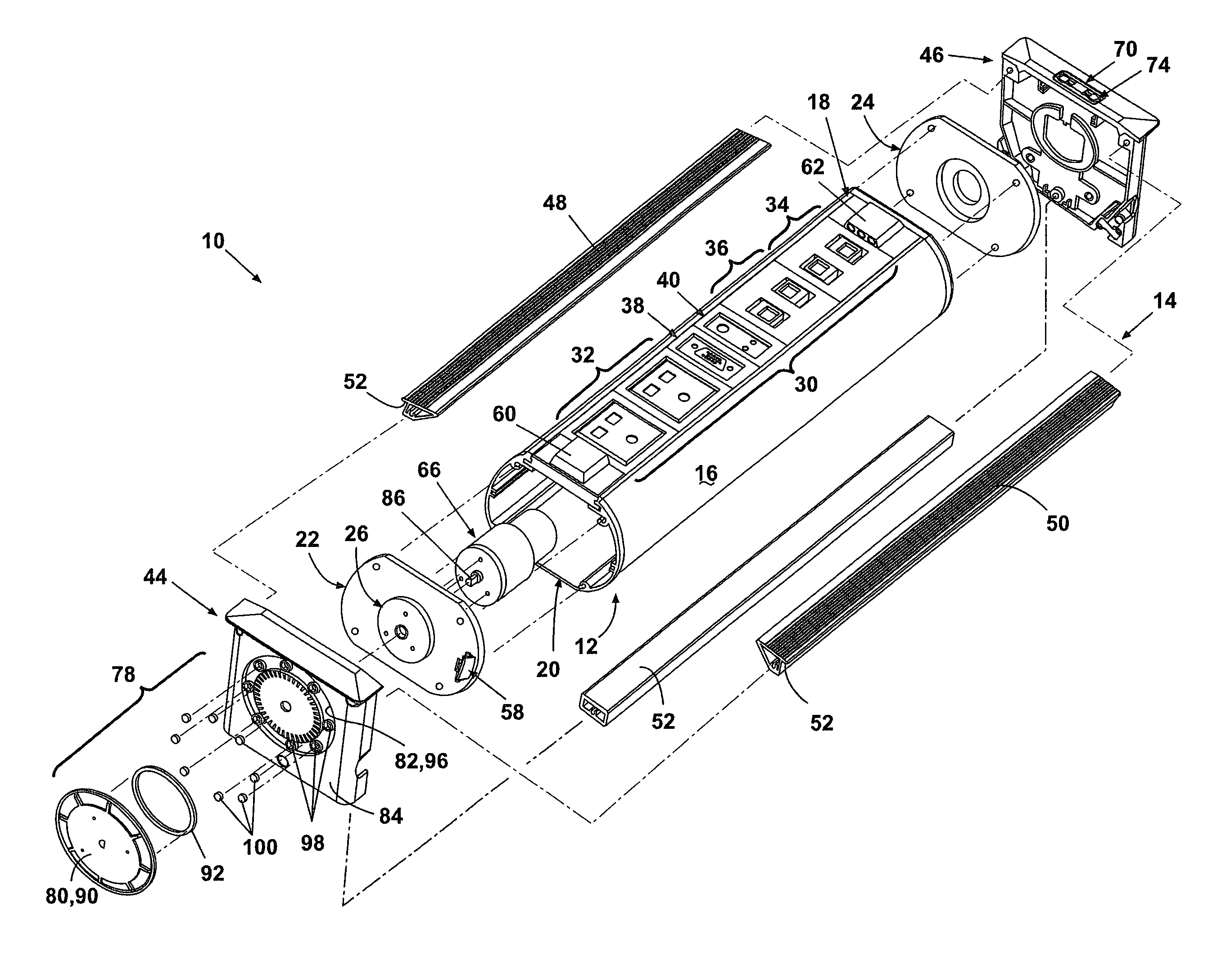
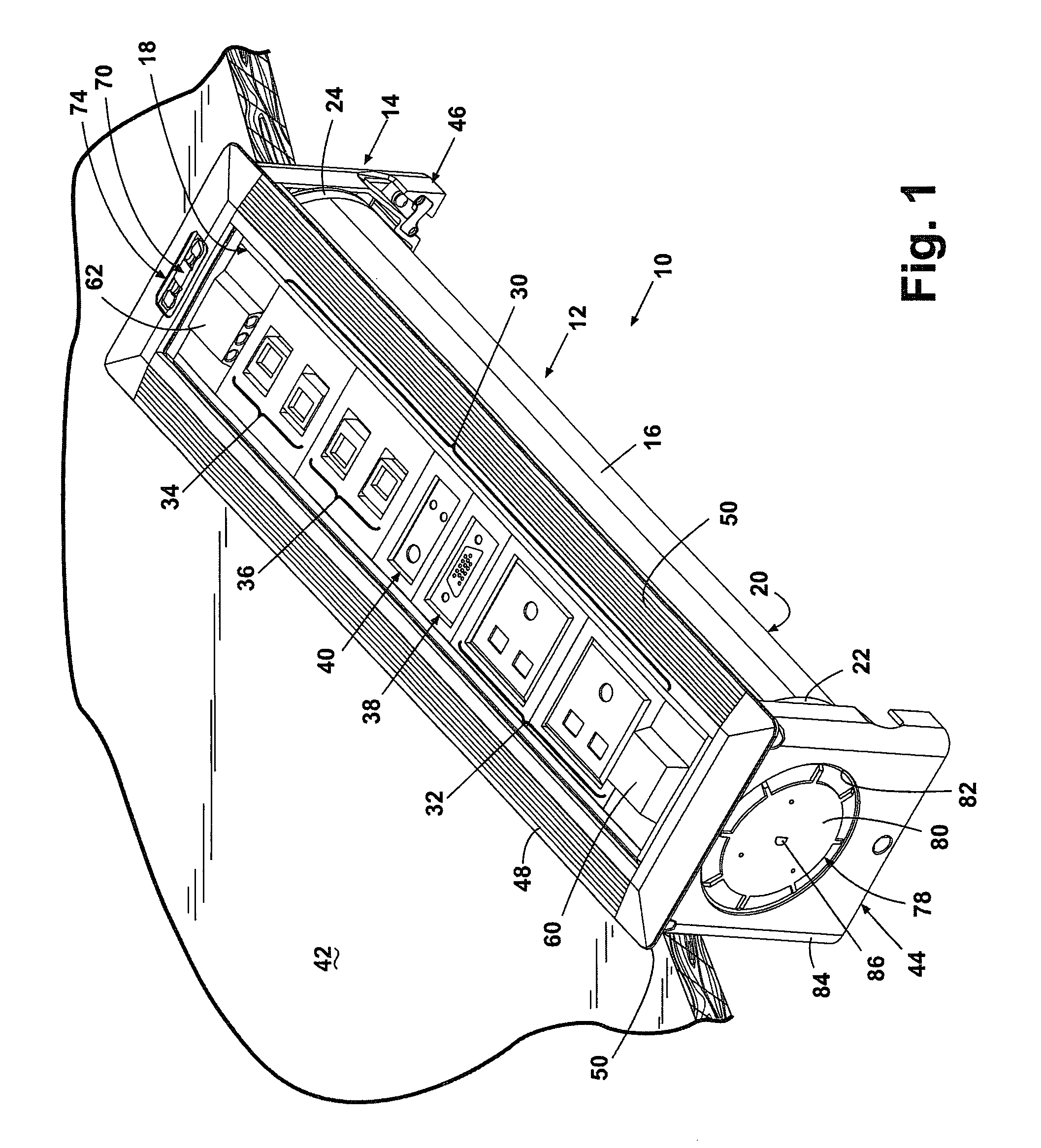
[0039]FIG. 4 is an end elevation view of the assembly 10. FIG. 5 is a section view of the assembly 10 taken along line V-V shown in FIG. 4. In order to promote rotation of the drum assembly 12, the rotation control assembly 56 within the drum assembly 12 rotates the drum assembly 12 about its longitudinal axis relative to the frame assembly 14. The rotation control assembly 56 includes detectors 60 and 62 that use an optical signal to determine whether at least one of the receptacles 30 is being used. The control circuit assembly 64 performs its control functions based on the optical signals received from the detectors 60 and 62. The control circuit assembly 34 controls the rotary direction of the motor assembly 66 and the supply of power to the motor assembly 66. The housing of the motor assembly 66 is fixed with respect to the tubular body 16 of the drum assembly 12, while the end of the motor assembly shaft is substantially fixed with respect to the end member 44. The motor assem...
example 2
[0042]Another embodiment of the invention may be understood by reference to FIGS. 5-7. In the second embodiment, modifications have been to the workings of the rotation disk or clutch plate 80 attached to the end member 44 described above. Another difference lies in the design of the frame assembly 14 as described below.
[0043]In the embodiment shown in FIGS. 5-7, the surface 88 of the rotation disk or clutch 90 includes a metal annulus or ring 92 which is facing toward the bottom wall 94 of the recess or depression 96 formed in the end member 44. The bottom wall or surface 94 of the recess 96 proximate the annulus 92 includes a plurality of lesser recesses 98 spaced substantially equidistantly angularly around the clutch engaging surface 94. Within each recess is fixed a magnet 100 so that the metal annular ring or surface 92 is magnetically attracted toward each magnet 100. The metal annulus 92 and the rotation disc or clutch plate 90 are pulled firmly against the end member 44 by ...
PUM
 Abstract
Description
Claims
Application Information
 - R&D
- Intellectual Property
- Life Sciences
- Materials
- Tech Scout
- Unparalleled Data Quality
- Higher Quality Content
- 60% Fewer Hallucinations
Browse by: Latest US Patents, China's latest patents, Technical Efficacy Thesaurus, Application Domain, Technology Topic, Popular Technical Reports.
© 2025 PatSnap. All rights reserved.Legal|Privacy policy|Modern Slavery Act Transparency Statement|Sitemap|About US| Contact US: help@patsnap.com