Wound retractor

a retractor and wound technology, applied in the field of wound retractors, can solve the problems of limited use, difficult and cumbersome use and relatively high cost of conventional wound retractors

Inactive Publication Date: 2011-09-20
ATROPOS LTD
View PDF439 Cites 74 Cited by
  • Summary
  • Abstract
  • Description
  • Claims
  • Application Information

AI Technical Summary

Benefits of technology

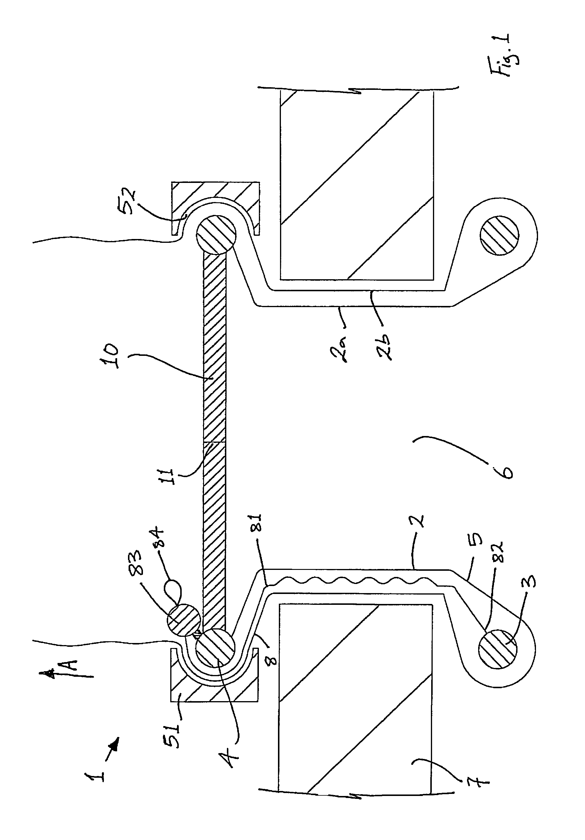
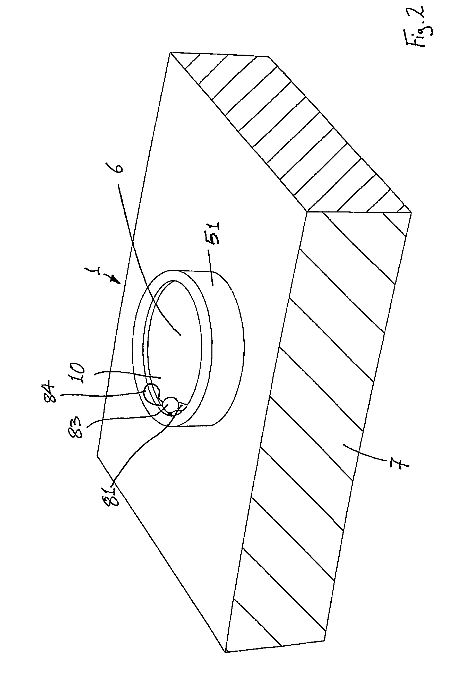
[0014]In another embodiment the retractor comprises a valve. The valve maintains gas pressure within the interior of the wound opening even when the wound opening is retracted. The valve may be mounted to the proximal member. The valve may be at least partially of a gelatinous elastomeric material. The valve may comprise a gelatinous elastomeric material portion and a housing portion. The housing portion may be mounted to the proximal member. The valve may comprise an opening extending therethrough. The opening through the valve facilitates access for instruments to pass through the valve and the retracted wound opening to access the interior of the wound opening. The opening may be biased towards a closed configuration. The opening is biased towards the closed configuration to minimise loss of gas pressure upon exchange of instruments through the opening. The opening may comprise a pinhole. The valve may be an instrument seal.
[0109]pulling the retractor member axially relative to the proximal member to draw the proximal and distal members towards one another thereby shortening the axial extent of the retractor member between the proximal and distal members and retracting the incision.

Problems solved by technology

Some conventional wound retractors are difficult and cumbersome to use, and / or are relatively expensive.
In addition, some conventional wound retractors are limited to use with a particular size of incision and a particular patient anatomy.

Method used


Image

  • Wound retractor
  • Wound retractor
  • Wound retractor

Examples


Embodiment Construction

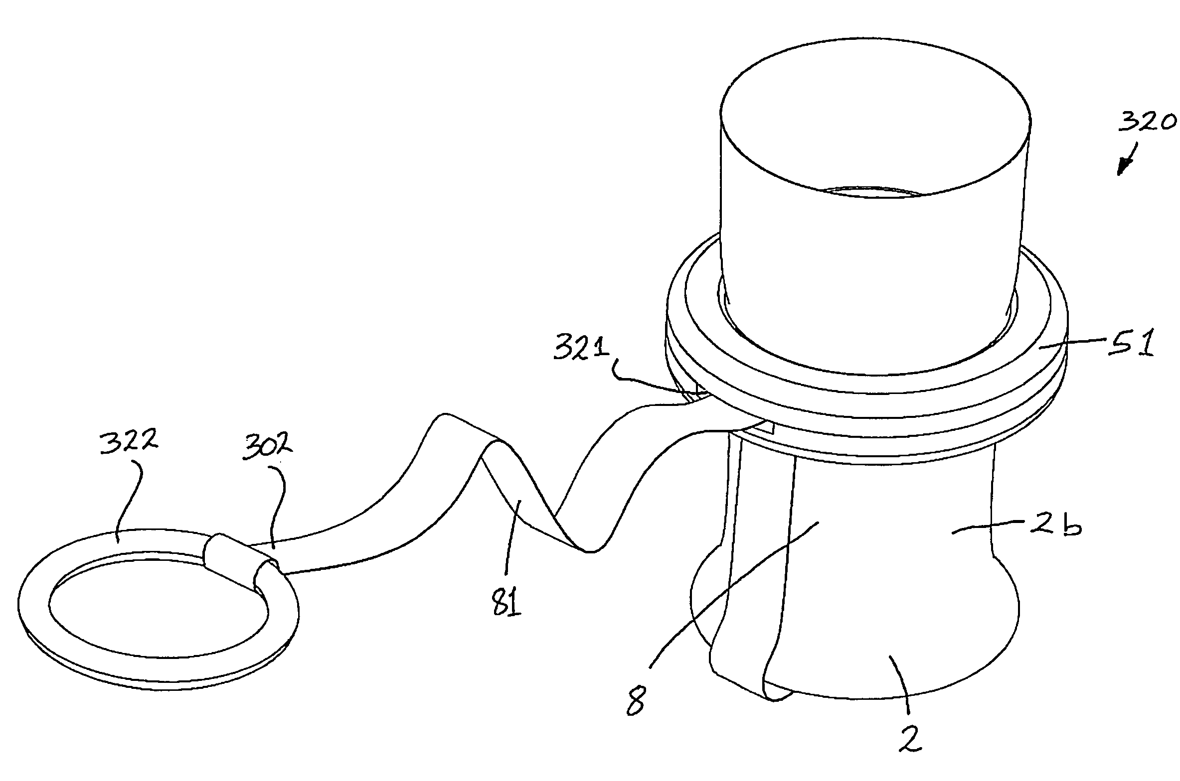
[0121]Referring to the drawings, and initially to FIGS. 1 to 4 thereof, there is illustrated a wound retractor 1 according to the invention, which comprises a retractor member provided by a sleeve 2, an elastomeric distal member provided by a distal ring 3 of resilient material such as an O-ring, and a relatively rigid proximal member provided by a proximal ring 4 which may also be an O-ring. The distal member 3 is suitable for insertion through a wound opening or incision 6, and the proximal member 4 is suitable for location externally of the wound opening / incision 6.

[0122]The sleeve 2 is of any suitable material such as of pliable plastics film material and comprises a distal portion 5 for insertion through the incision 6, in this case made in a patient's abdomen 7, and a proximal portion 8 for extending from the incision 6 and outside of the patient.

[0123]In this case the distal ring 3 is not fixed to the sleeve 2 but rather the sleeve 2 is led around the ring 3 and is free to mo...


PUM


Abstract

A wound retractor (320) comprises a distal ring (3) for insertion through a wound opening (6), a proximal ring (4) for location externally of the wound opening (6), a valve (10) mounted to the proximal ring (4), and a sleeve (2) for retracting laterally the sides of the wound opening (6). The wound retractor (320) also comprises a flexible release member (81) for releasing the distal ring (3) from a retracting configuration for removal of the distal ring (3) from the wound opening (6). A first end (301) of the release member (81) is attached to the valve housing (102), the release member (81) loops around the distal ring (3), and a second end (302) of the release member (81) is movable relative to the proximal ring (4) to release the distal ring (3) from the retracting configuration.

Description

[0001]This application is a Continuation-In-Part of U.S. application Ser. No. 10 / 678,653, filed Oct. 6, 2003 now U.S Pat. No. 7,559,893. U.S. application Ser. No. 10 / 678,653 also claims the benefit of U.S. Provisional Application Nos. 60 / 415,780, filed on Oct. 4, 2002; 60 / 428,215, filed on Nov. 22, 2002; and 60 / 490,909, filed on Jul. 30, 2003.[0002]This application also claims the benefit of U.S. Provisional Application Nos. 60 / 699,371 filed on Jul. 15, 2005, and 60 / 724,785 filed on Oct. 11, 2005.INTRODUCTION[0003]This invention relates to a wound retractor. In particular this invention relates to a wound retractor for retracting laterally the sides of a wound opening to provide maximum exposure of an organ or body structures for examination and / or access for surgical procedures.[0004]Some conventional wound retractors are difficult and cumbersome to use, and / or are relatively expensive. In addition, some conventional wound retractors are limited to use with a particular size of inc...

Claims


Application Information

Patent Timeline
Patent Type & Authority Patents(United States)
IPC IPC(8): A61B1/32
CPCA61B17/3423A61B17/0293A61B17/3431A61B17/02A61B2017/3492A61B2017/00557A61B2017/3482A61B2017/3484
Inventor BONADIO, FRANKBUTLER, JOHNDEEGAN, CATHERINEVAUGH, TREVOR
Owner ATROPOS LTD
Why Eureka
Try Eureka