Prosthesis heart valve fixturing device

a heart valve and prosthesis technology, applied in the field of prosthesis heart valve fixation device, can solve the problems of increased health risks due to heart-lung bypass, time-consuming procedure, and increased risk of complications including permanent health damag

Inactive Publication Date: 2011-09-20
MEDTRONIC INC
View PDF697 Cites 155 Cited by
  • Summary
  • Abstract
  • Description
  • Claims
  • Application Information

AI Technical Summary

Problems solved by technology

This procedure is time consuming as doctors often use three to ten knots per suture.
The longer a patient is on heart-lung bypass, the greater the risk for complications including permanent health damage.
Existing suturing techniques extend the duration of bypass and increase the health risks due to heart-lung bypass.
Furthermore, the fixturing force created by suturing varies significantly because the pre-tensioning of the suture just prior to knot tying is difficult to consistently maintain, even for the same medical professional.

Method used


Image

  • Prosthesis heart valve fixturing device
  • Prosthesis heart valve fixturing device
  • Prosthesis heart valve fixturing device

Examples


Embodiment Construction
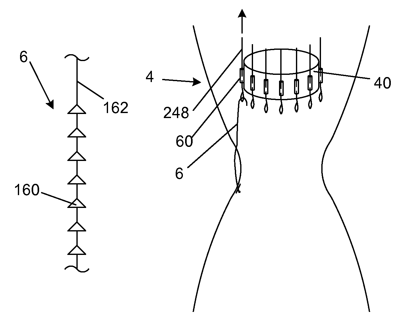
Fixturing Devices

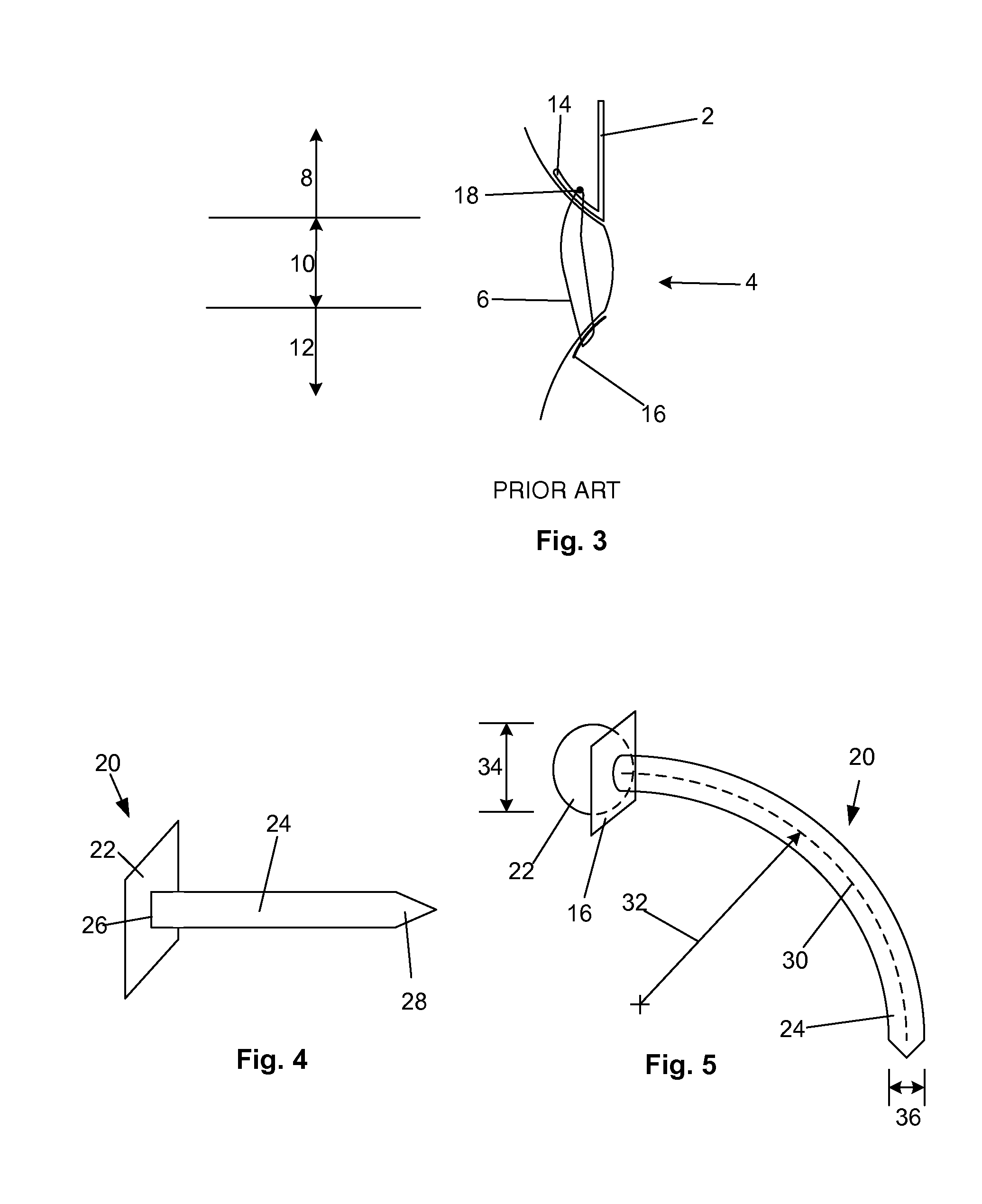
[0105]FIG. 4 illustrates an attachment or fixturing device 20, for example a brad (e.g., single brad, double-brad, quadruple brad), stud, spike, staple, barb, hook or any combination thereof. The fixturing device 20 can have a base 22 and a connector, for example a connecting protrusion 24. The base 22 can be solid and / or substantially spherical. The base 22 can have a radially expandable portion, as described in in U.S. patent application Ser. No. 10 / 327,821 filed 20 Dec. 2002, which is herein incorporated by reference in its entirety. The protrusion 24 can have a first end 26 and a second end 28. The first end 26 can be fixedly attached to the base 22. The second end 28 can be sharpened or pointed.

[0106]The fixturing device 20 can be used to attach a prosthesis to a first mass. The prosthesis can be, for example, stents, grafts, stent-grafts, heart valves, annuloplasty rings autografts, allografts, xenografts or any combination thereof. The first mass can be, for ...


PUM


Abstract

A biologically implantable prosthesis is disclosed. The prosthesis can have a circumferentially expandable wall and elements that prevent the wall from collapsing once the wall is expanded. Methods of making and using the prosthesis are also disclosed.

Description

BACKGROUND OF THE INVENTION[0001]1. Field of the Invention[0002]The present invention relates generally to a device for fixturing a prosthesis to a first mass and methods of making and using the same.[0003]2. Description of the Related Art[0004]Prosthetic heart valves can replace defective human valves in patients. Prosthetic valves commonly include sewing rings or suture cuffs or rings that are attached to and extend around the outer circumference of the prosthetic valve orifice.[0005]In a typical prosthetic valve implantation procedure, the aorta is incised and the defective valve is removed leaving the desired placement site that may include a fibrous tissue layer or annular tissue. Known heart valve replacement techniques include individually passing sutures through the fibrous tissue or desired placement site within the valve annulus to form an array of sutures. Free ends of the sutures are extended out of the thoracic cavity and laid, spaced apart, on the patient's body. The f...

Claims


Application Information

Patent Timeline
Patent Type & Authority Patents(United States)
IPC IPC(8): A61F2/24A61B17/00A61B17/04A61B17/06A61F2/02
CPCA61B17/0401A61F2/2409A61F2/2412A61B2017/00243A61B2017/0406A61B2017/0417A61B2017/0496Y10T29/49826A61F2/2415A61F2002/30545A61F2250/001A61B2017/0608
Inventor FOGARTY, THOMAS J.DREWS, MICHAEL J.LANE, ERNESTHOLMGREN, NEILGUITERREZ, FEDERICO
Owner MEDTRONIC INC
Why Eureka
Try Eureka