Apparatus and method for improved handover in mesh networks

a mesh network and handover technology, applied in the field of apparatus and a method for improving handover in mesh networks, can solve problems such as service disruption and disconnection of connectivity, and achieve the effects of avoiding connectivity loss, efficient adapting, and avoiding connectivity loss

Active Publication Date: 2011-09-20
NTT DOCOMO INC
View PDF5 Cites 37 Cited by
  • Summary
  • Abstract
  • Description
  • Claims
  • Application Information

AI Technical Summary

Benefits of technology

[0008]In multi-hop wireless access networks in many cases it is advantageous if a (preferably but not necessarily complete) tree or subtree of nodes performs a co-ordinated handover. As nodes rely on other nodes for access to an AP, they need to co-ordinate such handovers to avoid that the other nodes which are connected to the node which is going to perform a handover are adversely affected. By performing a co-ordinated handover for a tree or subtree the loss of connectivity can be avoided. E.g. if the root of a such a tree or subtree, say B, does a handover, then the complete sub-tree of nodes which connect to an AP through node B performs a handover as well. This avoids the connectivity losses which would arise if B alone would perform a handover. Moreover, the complete handover for a tree of nodes enables it to take into account radio resource management considerations such as to efficiently adapt to changes of radio resource management parameters like the available frequencies at access points which could act as handover camdidates, the load in the radio infrastructure, signal strength, available services, or the like.
[0009]The handover being performed in a “co-ordinated fashion” may mean that the handover is executed by the tree members in a sequential fashion whereas the sequence is chosen such that there is no connectivity loss or such that the connectivity loss is minimised. This may be done by performing the sequential handover such that the sequence is chosen according to the position of a terminal (or node) in the tree, starting with the root and then going downstream along the tree until the leafs are reached. Another possibility would be to execute the handover for the tree members simultaneously, preferably at a predefined moment of time. This may encompass some connectivity loss, however, in this case the time necessary to perform the complete handover is minimised.
[0012]This allows a co-ordinated handover in an almost simultaneous manner with minimum losses in connectivity.
[0014]The generation and upstream forwarding of a handover request message is an efficient way of finding the root node of the tree the nodes of which should participate in the handover. Through the multi-hop structure of the mesh network this allows the identification of the individual elements of the tree as those elements through which the message passes up to the root node.
[0019]According to one aspect the various access points in said mesh network respectively maintain a table about the different APs and the relevant parameters for determining said second access point as a handover candidate. Such parameters may include the frequencies of the respective access points, their “visibility” which means information about which nodes in the network can reach them, either directly or via other nodes, their actual and maximum load, the services offered by them, and the like. This ensures that the access points always are aware about the available access points and their respective capabilities, and it thereby enables the decision to which access point the handover should be made to be made in an efficient and well-founded manner.
[0025]According to one aspect said downstream message includes timing information to enable a co-ordinated handover of said nodes of said tree. This makes it possible to perform the handover of the tree nodes in a co-ordinated manner thus minimising the connectivity losses due to the handover. The timing information could be explicitly specified, e.g. by a moment in time at which the handover should be performed, or it could be implicitly specified, e.g. by triggering the handover as the message is received.

Problems solved by technology

However, if nodes do individual handover, connectivity breaks and nodes may have to discover AP's from scratch.
This would lead to service disruptions.

Method used


Image

  • Apparatus and method for improved handover in mesh networks
  • Apparatus and method for improved handover in mesh networks
  • Apparatus and method for improved handover in mesh networks

Examples


Embodiment Construction

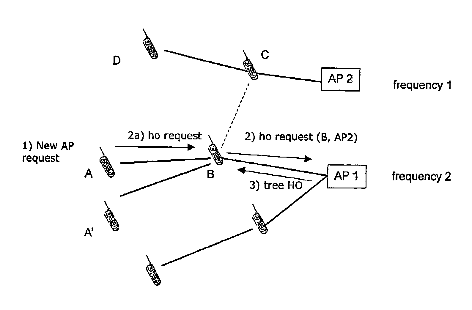
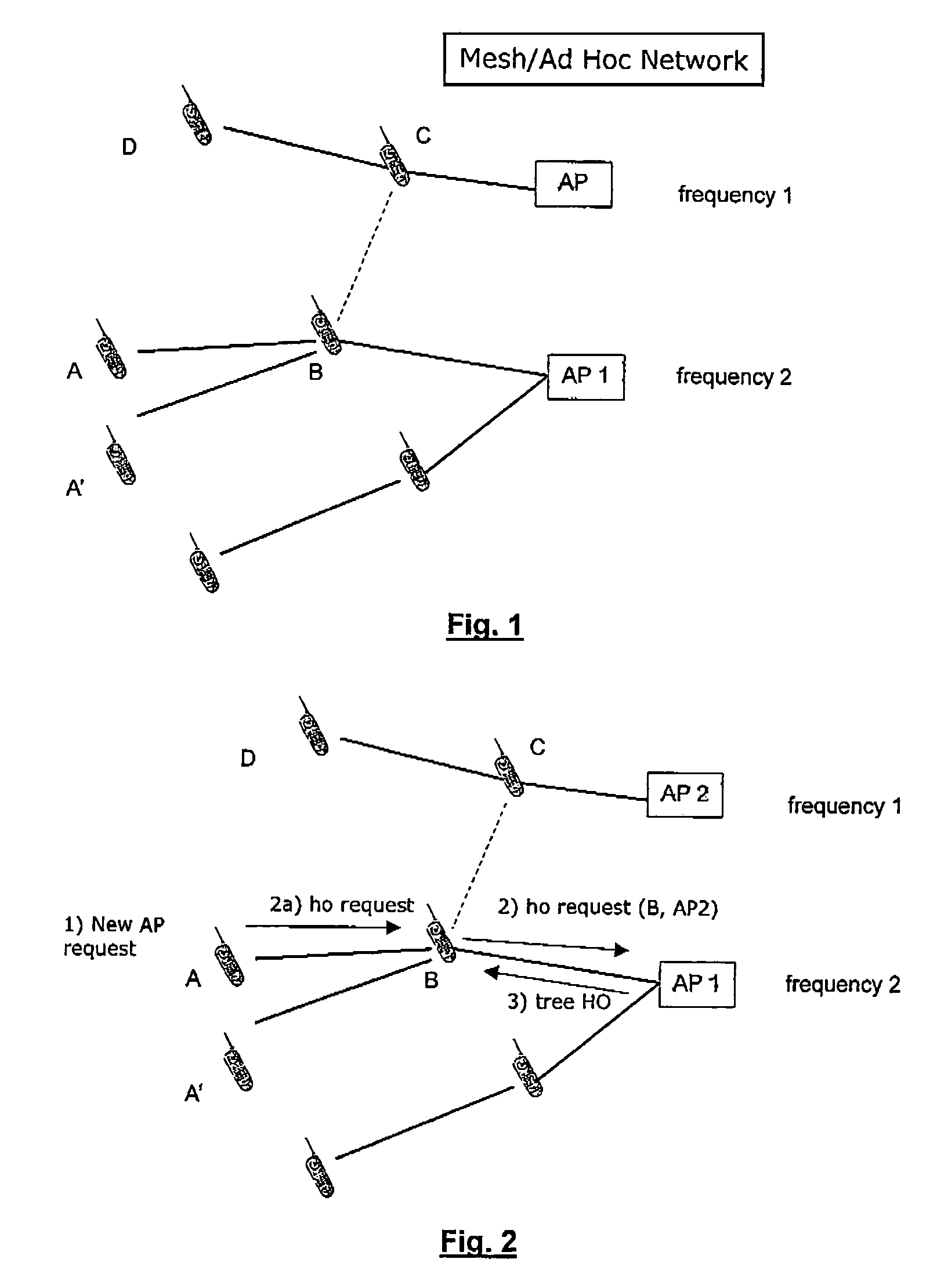
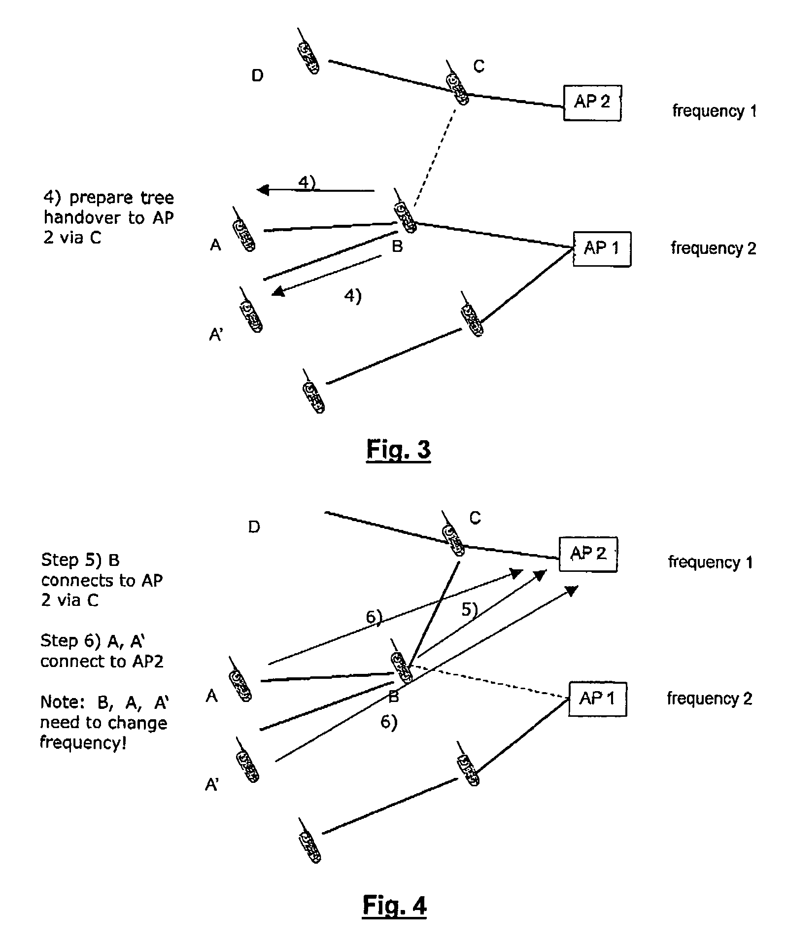
[0041]FIG. 1 illustrates a method for a handover in a mesh network according to a first embodiment of the invention. In this embodiment it is assumed that the two access points AP1 and AP2 operate at different frequencies. In this embodiment it can be beneficial to perform a handover for a tree or a sub-tree in several cases.

[0042]Examples of such cases are[0043]1. If node B needs to join AP2 with different frequency, A and A′ need to join as well—otherwise they (possibly) cannot connect to any AP. This may e.g. be due to the fact that they are located outside the area covered by AP1 and possibly any other access point as well so that their only possibility not to loose connection is to connect to an access point through node B. This means A and A′ need to change frequency as well.[0044]2. If A needs to join AP2, e.g. due to other features available at AP2, the node B (and possibly A′) need to join as well. The reason may be the same as in case 1, namely that node A alone may not be...


PUM


Abstract

A method for performing a handover in a mesh network for a plurality of nodes (A, A′, B) of said mesh network from a first access point (AP1) to a second access point (AP2), whereas said plurality of nodes (A, A′, B) forms a tree of nodes, said tree comprising a root node (B) and one or more further nodes (A,A′) connected to said root node either directly or via intermediate nodes, and said handover being performed for said tree of nodes in a coordinated fashion, said method comprising:forwarding to said members of said tree (A, A′, B) information about said second access point (AP2) and timing information to enable a coordinated handover of said nodes of said tree;switching said root node (B) and said further (A,A′) nodes from said first access point to said second access point according to said timing information.

Description

FIELD OF THE INVENTION[0001]The present invention relates to and apparatus and a method for improved handover in mesh networks.BACKGROUND OF THE INVENTION[0002]In multi-hop wireless access networks, also called mesh networks, mobile nodes connect via other nodes to access points. The nodes are connected via some wireless links and reach other nodes in the mesh via some (ad-hoc) routing protocol. In addition, each node is registering via some access protocol to an access point (AP) for global connectivity. This creates a tree for each AP, where the AP (or the node directly connected to the AP) is the root. Nodes may change between APs due to mobility or other reasons, such as features of an AP or radio resource management.[0003]FIG. 1 schematically illustrates an environment of a mesh network where there are two different access points AP1 and AP2 which may have different frequencies. One can recognize that nodes A and A′ connect to access point AP1 via node B. This means that nodes ...

Claims


Application Information

Patent Timeline
Patent Type & Authority Patents(United States)
IPC IPC(8): G08C17/00H04W36/08H04W84/00
CPCH04W36/0055H04W84/18
Inventor PREHOFER, CHRISTIAN
Owner NTT DOCOMO INC
Why Eureka
Try Eureka