
Image forming apparatus and image forming method

a technology of image forming apparatus and forming method, which is applied in the direction of electrographic process apparatus, instruments, optics, etc., can solve the problems of difficult to successfully remove the transfer material, difficult to appropriately and stably hold the transfer material, and failure to remove the transfer material successfully

Inactive Publication Date: 2011-09-20
SEIKO EPSON CORP
View PDF6 Cites 7 Cited by
  • Summary
  • Abstract
  • Description
  • Claims
  • Application Information

AI Technical Summary

Benefits of technology

[0009]An advantage of some aspects of the invention is that it provides an image forming apparatus and an image forming method which are adapted to appropriately and stably hold a transfer material before transfer in order to perform excellent image formation.
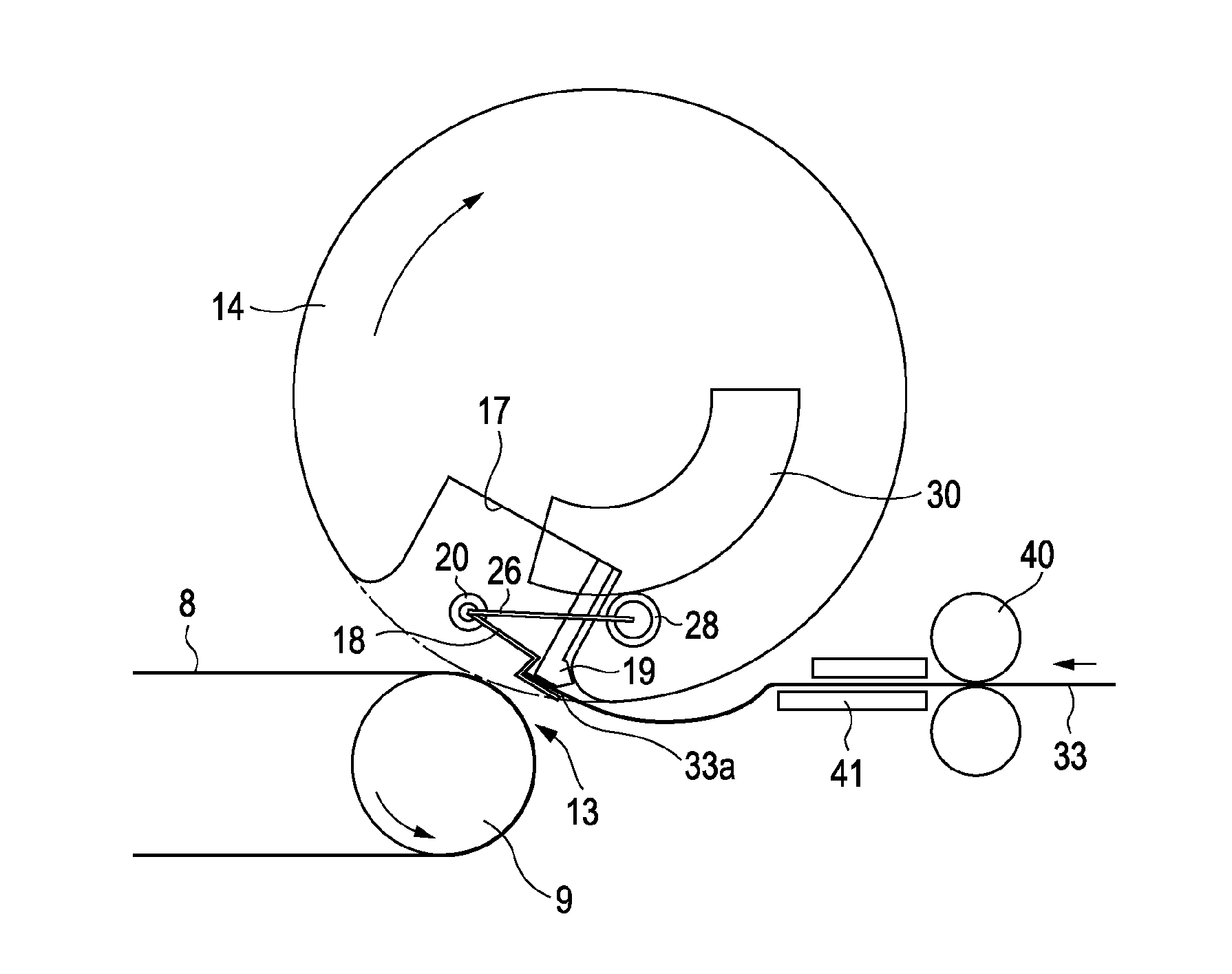
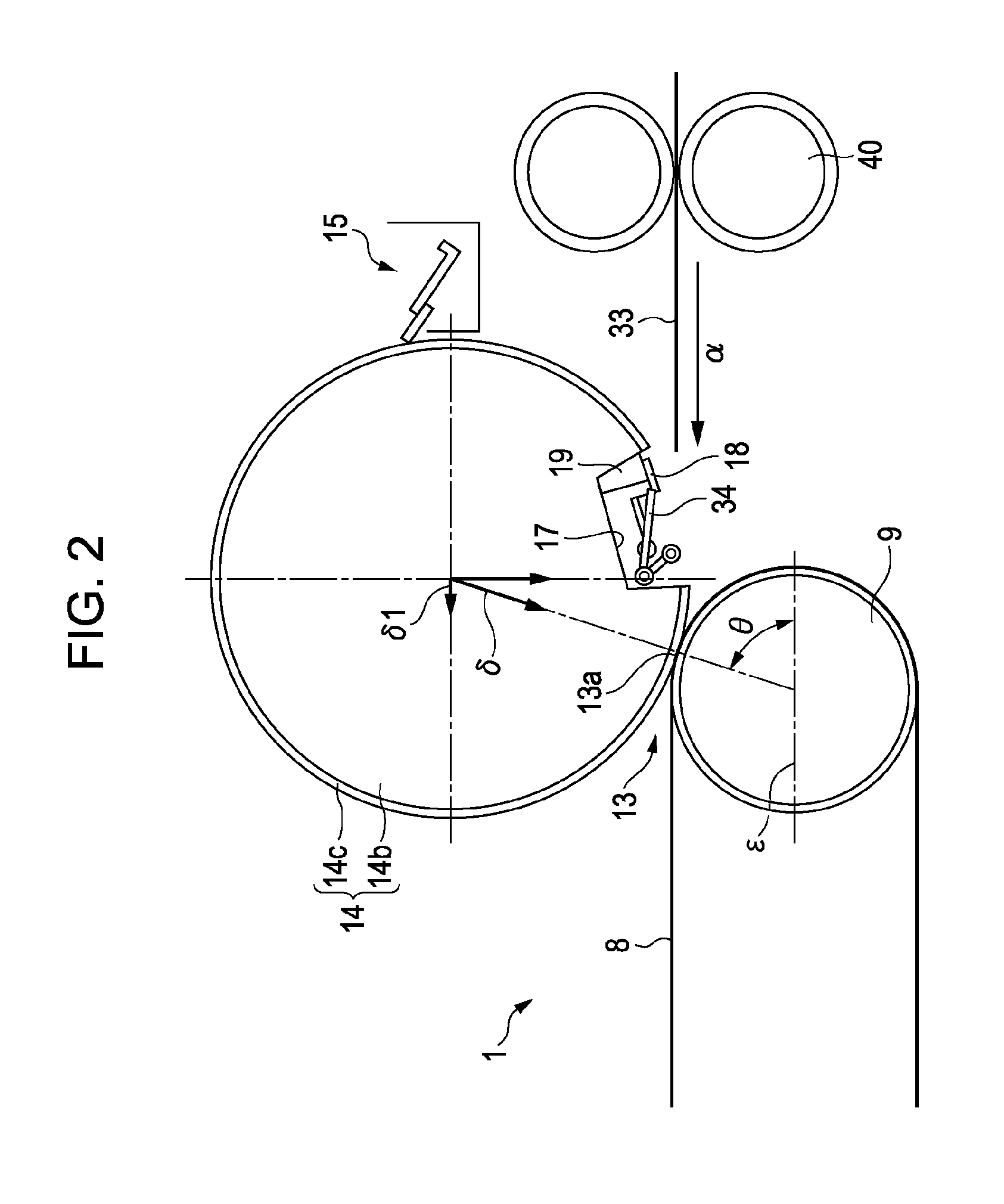
[0010]An image forming apparatus and an image forming method according to an aspect of the invention use a transfer roller. The transfer roller includes a holder member for holding a transfer material, a groove portion in which the holder member is disposed, and an elastic member disposed over the transfer roller except for a portion where the groove portion is disposed. The elastic member of the transfer roller is pressed onto an image carrier. According to the aspect of the invention, the image forming apparatus further includes a gate roller that transports the transfer material to the holder member of the transfer roller. A circumferential velocity v1 (mm / sec) of the elastic member of the transfer roller during a period over which the elastic member makes contact with a carrier is set to be lower than a moving speed v2 (mm / sec) of the transfer material. Accordingly, the transfer material is appropriately and stably held by the holder member at a predetermined position before transfer, after the transfer material is appropriately moved. Consequently, a secondary transfer is performed on the transfer material that is appropriately and stably held, which allows excellent image formation.
[0012]Further, in this aspect of the invention, pressing contact force by the transfer roller against the image carrier is directed to generate a vector component that is oriented toward the movement direction of the transfer material. Accordingly, when the transfer material is pinched between the transfer roller and the image carrier, the vector component effectively acts to pull the transfer material into a transfer nip. This allows the transfer material to be held by the holder member more appropriately and stably.
[0013]Further, this aspect of the invention includes a rotation speed detector and a controller. The rotation speed detector detects the rotation speed of the transfer roller. The controller controls the circumferential velocity of the transfer roller on the basis of the rotation speed of the transfer roller detected by the rotation speed detector. Accordingly, the circumferential velocity of the transfer roller can be controlled in accordance with the moving speed of the transfer material more precisely.

Problems solved by technology

However, the image forming apparatus disclosed in Japanese Patent No. 3128067 may fail to remove the transfer material successfully since the apparatus is adapted to merely blow the air to the tip end portion of the transfer material.
Therefore, it is difficult to appropriately and stably hold the transfer material being transported to the transfer drum by the holder member at a predetermined position of the transfer material.
Thus, it is difficult to successfully perform image formation with a combination of the technology for removing the transfer material disclosed in JP-A-3-4241 and the image forming apparatus disclosed in Japanese Patent No. 3128067.

Method used


Image

  • Image forming apparatus and image forming method
  • Image forming apparatus and image forming method
  • Image forming apparatus and image forming method

Examples


Embodiment Construction

[0025]An embodiment of the invention will be described hereinafter with reference to the drawings.

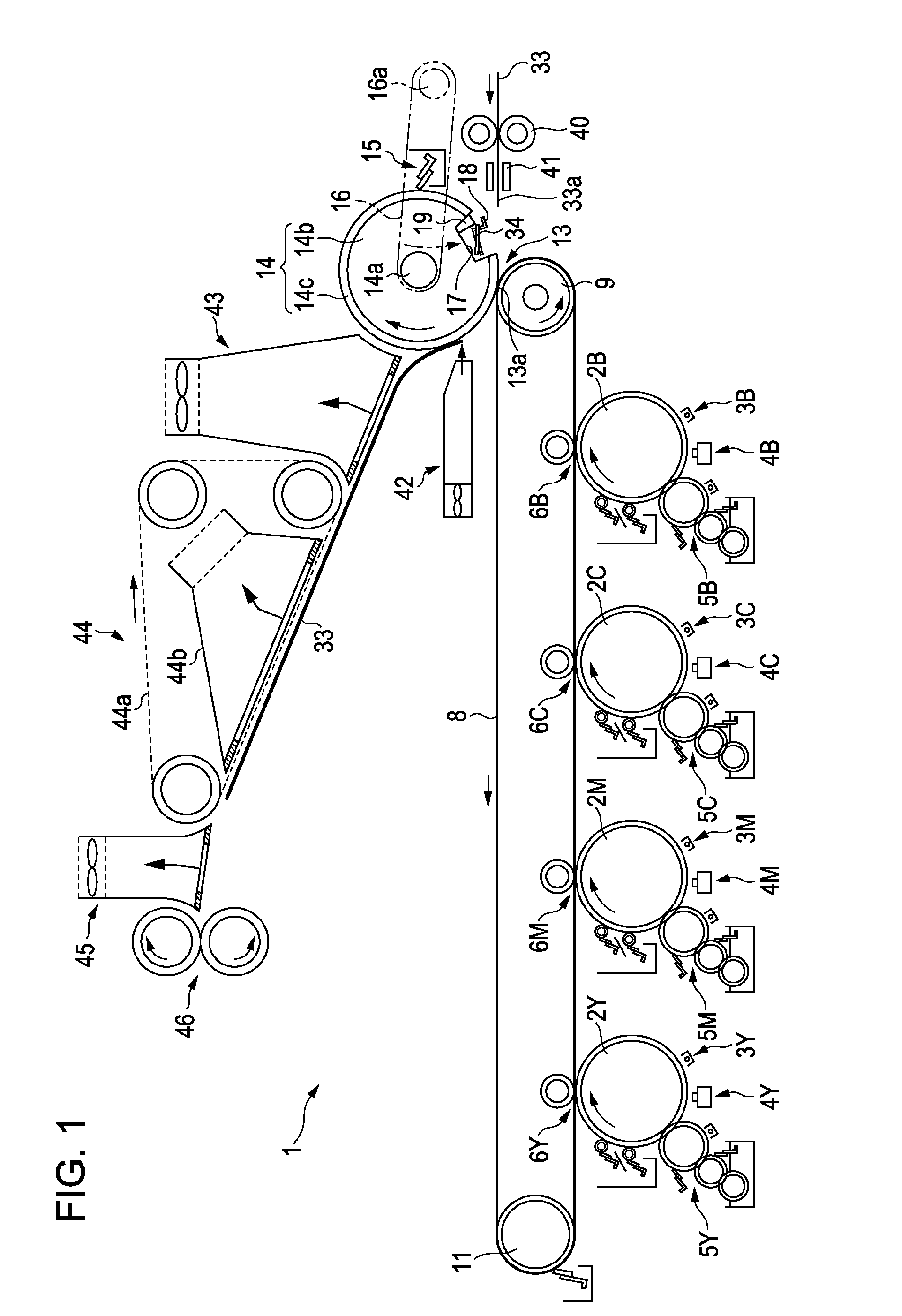
[0026]FIG. 1 is a schematic partial drawing showing an example of an embodiment of an image forming apparatus according to the invention.

[0027]The embodiment of the image forming apparatus 1 uses a liquid developer containing solid toner and carrier liquid to perform image formation. As shown in FIG. 1, the image forming apparatus 1 has photosensitive members 2Y, 2M, 2C, 2K that are image carriers of yellow (Y), magenta (M), cyan (C), and black (K), respectively, and that are disposed horizontally or generally horizontally. 2Y, 2M, 2C, 2K represent the photosensitive members of yellow, magenta, cyan and black, respectively. Other members of the image forming apparatus are also indicated with Y, M, C, K to represent the colors that the components are associated with.

[0028]Each of the photosensitive members 2Y, 2M, 2C, 2K is provided at its outer circumference with charged portions 3Y, 3M...


PUM


Abstract

An image forming apparatus, including: an image carrier for carrying an image; a transfer roller including a holder member that holds a transfer material, a groove portion in which the holder member is disposed, and an elastic member disposed over the transfer roller except a portion where the groove portion is disposed, the elastic member of the transfer roller is pressed onto the image carrier to transfer an image from the image carrier onto the transfer material; anda gate roller for transporting the transfer material to the holder member, whereina circumferential velocity v1 (mm / sec) of the elastic member of the transfer roller is lower than a moving speed v2 (mm / sec) of the transfer material transported by the gate roller.

Description

BACKGROUND[0001]1. Technical Field[0002]The present invention relates to an image forming apparatus for forming images. The apparatus includes a transfer roller that has a groove portion in which a holder member for holding a transfer material is provided. The transfer roller is pressed onto a carrier that carries images.[0003]2. Related Art[0004]In wet-type image forming apparatuses using liquid developer, a transfer material tends to stick onto an intermediate transfer member after transfer of toner images. This is because the transfer surface of the transfer material such as paper is pressed onto the intermediate transfer member. The transfer surface of the transfer material is a surface on which toner images are transferred. Accordingly, such an image forming apparatus has been proposed that is adapted to remove a transfer material from a transfer roller by blowing air to a tip end of the transfer material, after transfer (see, for example, Japanese Patent No. 3128067).[0005]Bes...

Claims


Application Information

Patent Timeline
Patent Type & Authority Patents(United States)
IPC IPC(8): G03G15/16
CPCG03G15/167G03G2215/0132
Inventor KAMIJO, KOICHI
Owner SEIKO EPSON CORP
Learn More