T1-corrected proton resonance frequency shift thermometry

a proton resonance and frequency shift technology, applied in the field of system and method of imaging tissue using magnetic resonance imaging, can solve the problems of phase shift, inability to measure absolute prf, and tumors that cannot be obscured by blood

Inactive Publication Date: 2011-09-20
GENERAL ELECTRIC CO
View PDF7 Cites 12 Cited by
  • Summary
  • Abstract
  • Description
  • Claims
  • Application Information

AI Technical Summary

Problems solved by technology

In addition, during the surgery, the tumor can be obscured by blood.
Because of a non-homogenous magnetic field within the MR image, absolute PRF measurements are not possible.
Unfortunately, movements of the object being imaged or dynamic changes in magnetic field intensity and / or uniformity during the MR imaging process (i.e., between successively acquired images) can also induce phase shifts, which can be misinterpreted as a temperature-induced phase shift.
This ambiguity makes it difficult to determine the tissue mass temperature change relying only on the MR signals from the tissue mass being heated.
Unfortunately, the temperature is these regions often do change, rendering the method ineffective.
The limitation here is that one may not have enough fatty tissues around to perform this correction.
In view of the foregoing, the problem of performing accurate measurement of temperature changes in tissue in an MRI system remains one of the biggest barriers to widespread use of the PRF method in temperature imaging.

Method used


Image

  • T1-corrected proton resonance frequency shift thermometry
  • T1-corrected proton resonance frequency shift thermometry
  • T1-corrected proton resonance frequency shift thermometry

Examples


Embodiment Construction

[0042]Referring to the drawings wherein identical reference numerals denote the same elements throughout the various views,

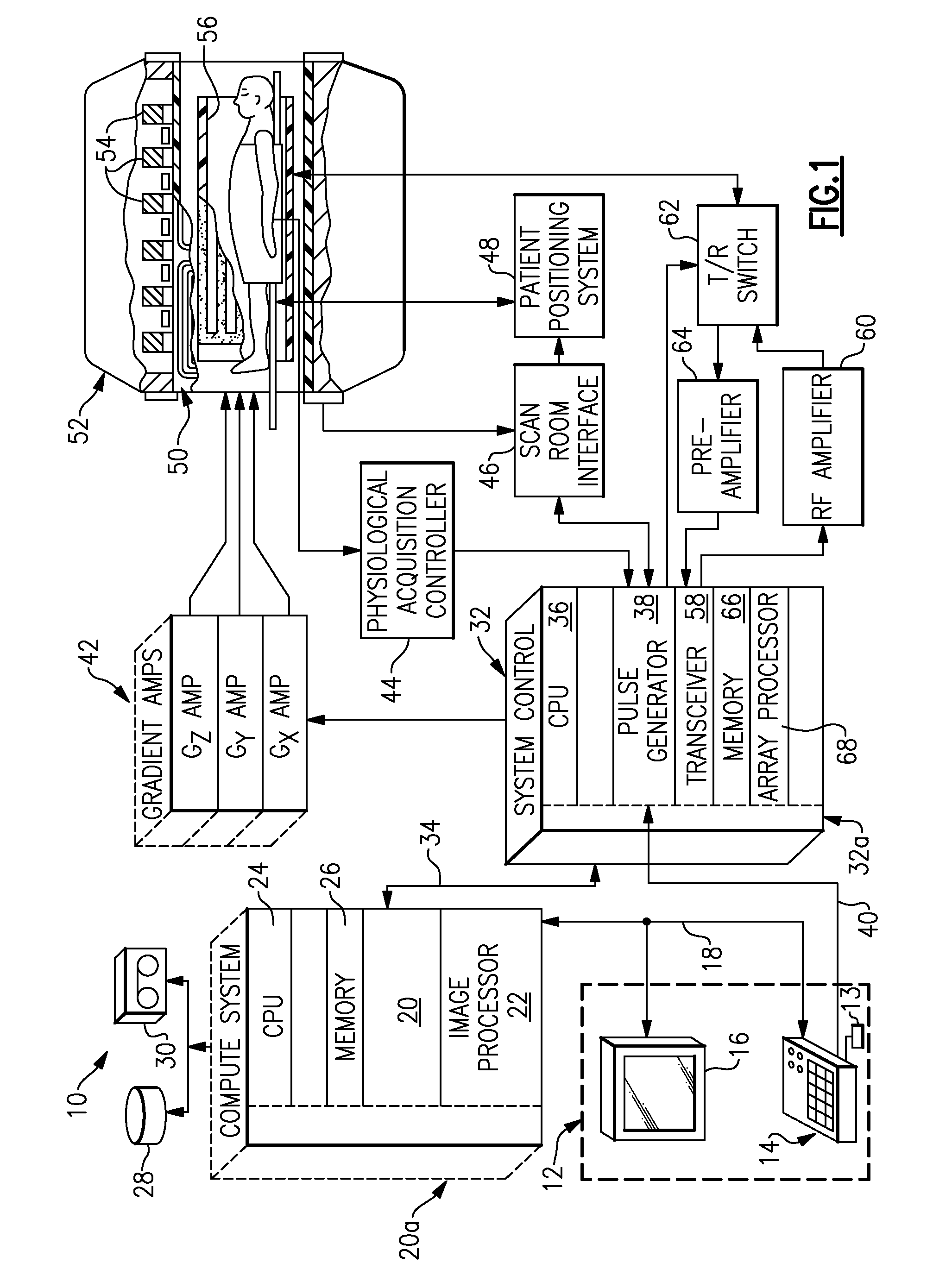
[0043]Referring to FIG. 1, a magnetic resonance imaging (MRI) apparatus 10 comprises a superconducting magnet system. An illustrative discussion of exemplary details of a magnetic resonance and / or magnetic resonance imaging (MRI) apparatus and / or system are presented for explanatory purposes only.

[0044]The operation of the MR apparatus is controlled from an operator console 12 which includes a keyboard or other input device 13, a control panel 14, and a display screen 16. The console 12 communicates through a link 18 with a separate computer system 20 that enables an operator to control the production and display of images on the display screen 16. The computer system 20 includes a number of modules which communicate with each other through a backplane 20a. These include an image processor module 22, a CPU module 24 and a memory module 26, known in the art as a ...


PUM


Abstract

An apparatus and method for correcting magnetic resonance temperature measurements is disclosed. In one aspect, the method identifies monitoring regions of interest outside a therapeutic region of interest. Next, a pulse sequence sensitive to changes in T1 and proton density is used to measure the temperature changes in these regions. Next, the PRFS is measured in these same regions. The PRFS in these regions will be caused both by the desired shift from temperature change, and the undesired shift from background magnetic field changes. Using the measured temperature changes from the T1-method, the component of the PRFS due to actual temperature changes is subtracted from the PRFS method, leaving only the component caused by the unwanted magnetic field changes. This analysis is performed separately for each region. At the end of this step, one has measured the change in background magnetic field within each region.

Description

BACKGROUND[0001]This invention relates generally to systems and methods for imaging tissue using magnetic resonance imaging (MRI) techniques, and more particularly to obtaining high accuracy temperature measurements of a tissue mass by compensating for errors during the acquisition of MR images used for temperature measurement by applying a T1-based correction to the MR images.[0002]In the past, ultrasound imaging has been used for both generating and positioning focused ultrasound waves on tissue to be destroyed. It was soon found that the MR images were much better suited for such guidance, since MR provides excellent images of tissue, and is not limited to “windows” that excludes bones, for example. Further, MRI system images are useful not only for guiding the actual surgical procedures, but also for planning the surgical procedures. In fact, a tumor is often much more visible in an MR image than as seen in actual surgery. In actual surgery, the tumor and normal tissues often lo...

Claims


Application Information

Patent Timeline
Patent Type & Authority Patents(United States)
IPC IPC(8): A61B5/05
CPCG01R33/4804G01R33/565G01R33/4808G01R33/5602G01R33/56509G01R33/56563
Inventor MALLOZZI, RICHARD PHILIPDUMOULIN, CHARLES LUCIAN
Owner GENERAL ELECTRIC CO
Why Eureka
Try Eureka