
Method for stratigraphic interpretation of seismic images

a stratigraphic interpretation and seismic image technology, applied in the direction of image analysis, image data processing, instruments, etc., can solve the problems of not being perfectly suited to seismic image interpretation, not being able to separate the analysis performed in a neighborhood placed, and often delicate interpretation stag

Inactive Publication Date: 2011-09-27
INST FR DU PETROLE
View PDF8 Cites 26 Cited by
  • Summary
  • Abstract
  • Description
  • Claims
  • Application Information

AI Technical Summary

Benefits of technology

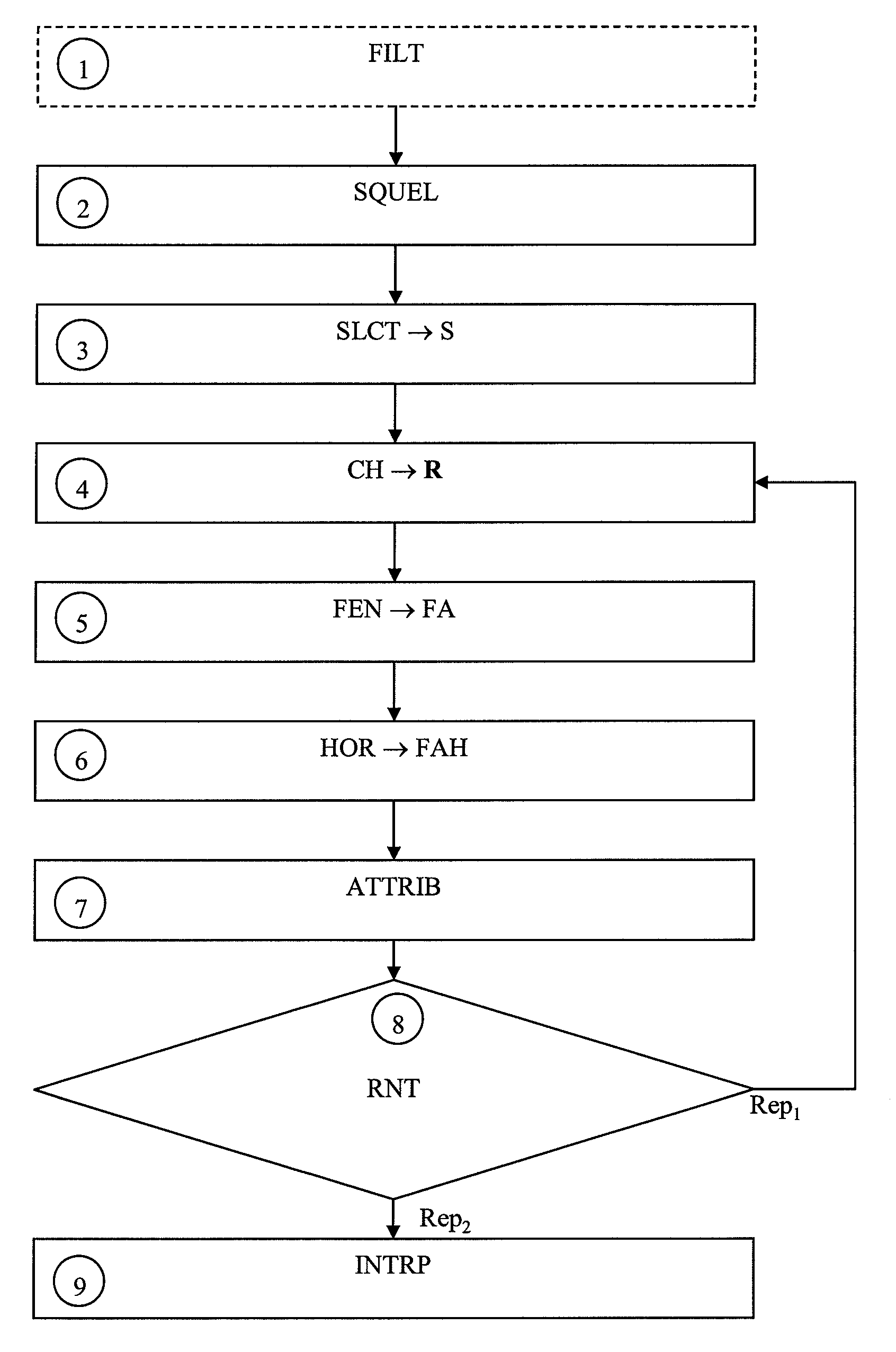
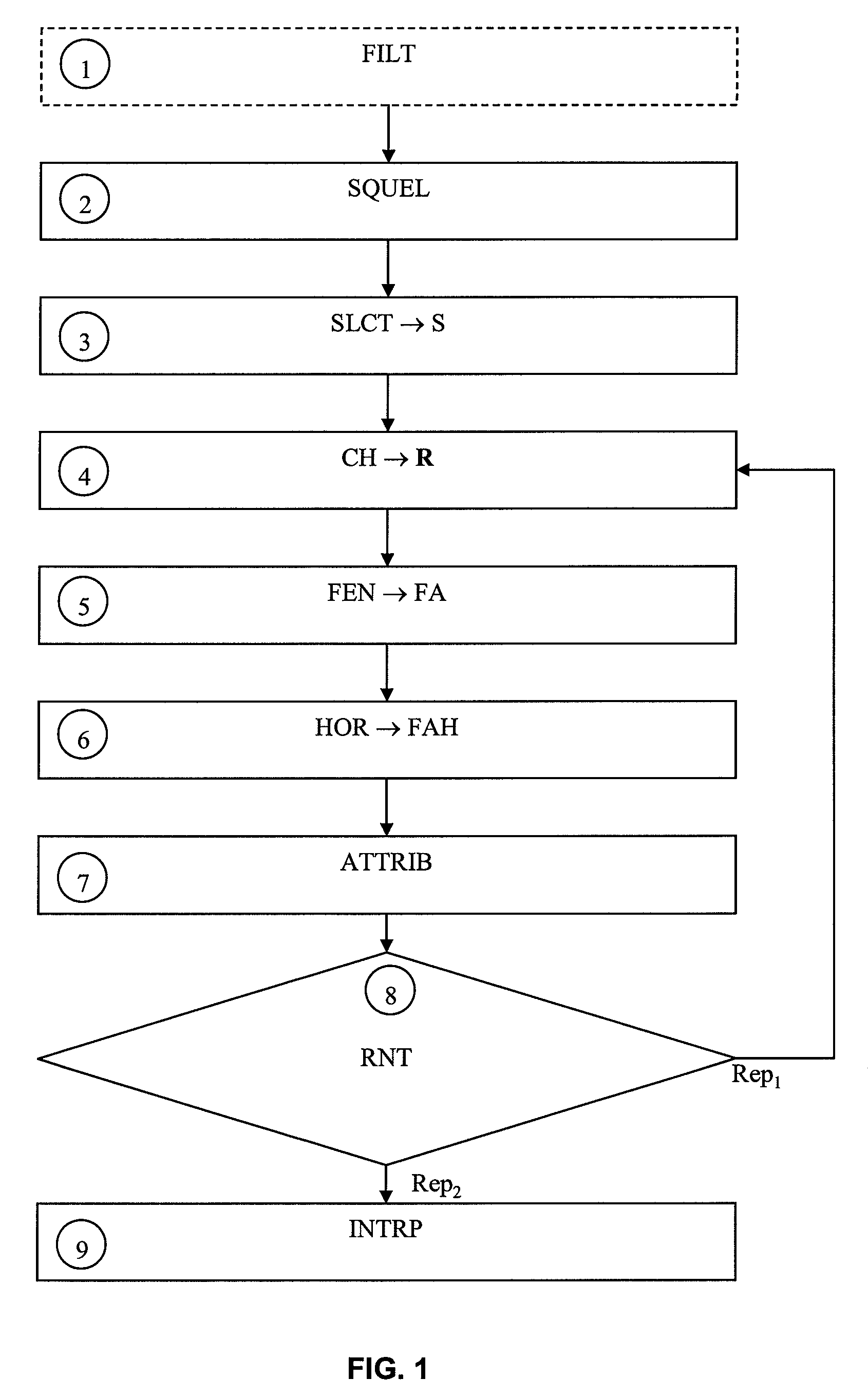
The invention is a method for interpreting seismic data to determine the sedimentary history of an underground zone. The method involves digitizing the seismic reflectors, calculating attributes of the image around each reflector, selecting relevant reflectors for interpretation, and reconstructing the sedimentary history of the underground zone from the selected reflectors. The method also includes applying a shape recognition technique to the image and using directional filtering to improve the accuracy of the interpretation. The invention provides a more accurate and reliable method for interpreting seismic data and understanding the sedimentary history of underground zones.

Problems solved by technology

The interpretation stage is often very delicate and it entirely depends on the interpreter's sedimentologic expertise.
There are few tools allowing assistance in this task, which with a more complex seismic image often shows several hundred reflectors in 2D and several thousands in 3D.
The methods presented above provide a transformation of the initial image that facilitates picking, but they do not perform this picking.
These methods work with mean values calculated in sliding neighborhoods of fixed and predetermined shape and size, which is not perfectly suited for seismic image interpretation.
The aforementioned methods do not allow separation of the analysis performed in a neighborhood placed according to the position of a reflector (completely above or completely below a reflector for example), because they do not involve the notion of “reflector”.

Method used


Image

  • Method for stratigraphic interpretation of seismic images
  • Method for stratigraphic interpretation of seismic images
  • Method for stratigraphic interpretation of seismic images

Examples


Embodiment Construction

[0058]The method according to the invention allows performing a stratigraphic interpretation of seismic data, that is to reconstruct the sedimentary history of an underground zone from seismic data in the form of 2D or 3D images.

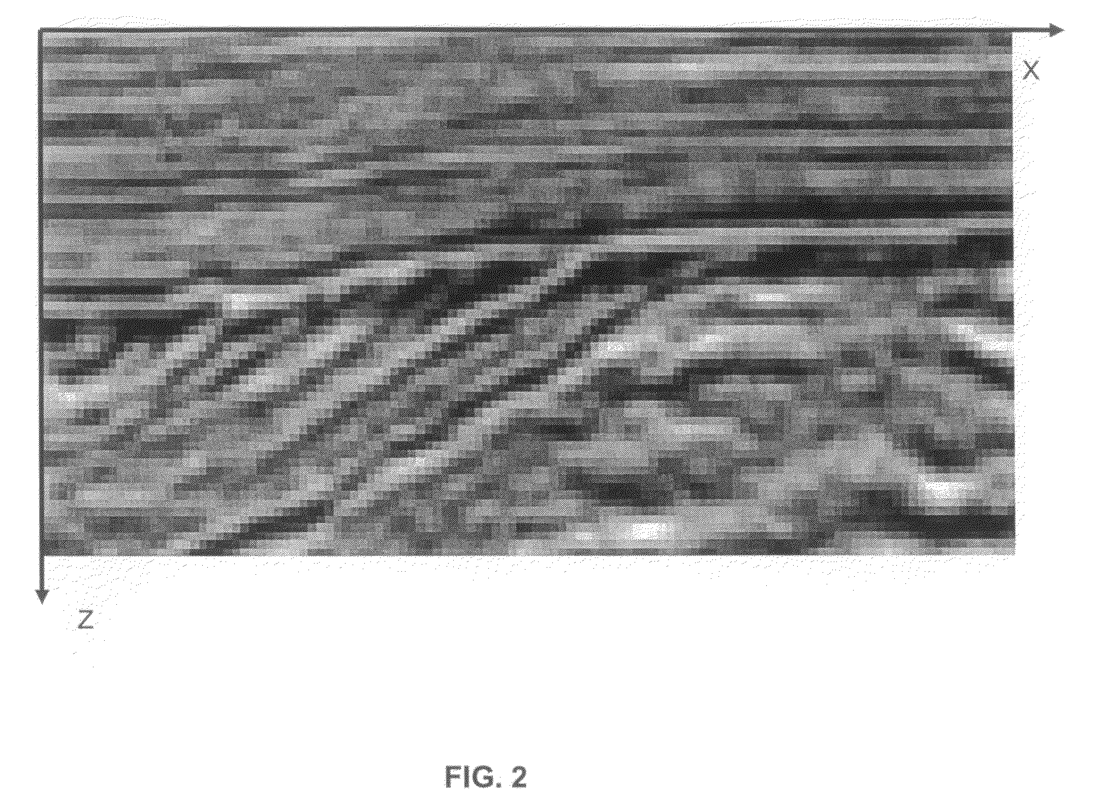
[0059]A seismic image is a set of pixels whose color depends on a value of the seismic data (seismic amplitude, impedance, . . . ) at the pixel to which a precise geographical location in the subsoil corresponds. These images comprise sub-horizontal lines, more or less rectilinear, thick and continuous, referred to as seismic reflectors.

[0060]The method allows characterization of the seismic data by parameters specific to each one of these seismic reflectors. The invention notably allows automatic separation of reflectors so as to extract pertinent characteristics for the stratigraphic interpretation. A characteristic is pertinent in the sense of seismic stratigraphy when it allows assessment of the sedimentary depositional conditions of an underground zone....


PUM


Abstract

A method for stratigraphic interpretation of a seismic image for determining a sedimentary history of an underground zone having application to petroleum exploration. The seismic reflectors of the image are digitized by means of an applied shape recognition technique. At least one attribute characteristic of the structure of the image in the vicinity of each reflector is calculated for a set of reflectors by means of an image analysis technique. This analysis is based on at least one analysis window whose shape is controlled by the associated reflector. Pertinent reflectors, in the sense of the stratigraphic interpretation, are selected from among this set of reflectors on the basis of this attribute. Finally, the sedimentary history of the underground zone is reconstructed from a stratigraphic interpretation of the reflectors thus selected.

Description

BACKGROUND OF THE INVENTION[0001]1. Field of the Invention[0002]The present invention relates to the sphere of stratigraphic interpretation of seismic data. More particularly, the invention relates to processes for automatic detection of seismic reflectors showing pertinent characteristics for seismic stratigraphy interpretation, such as sedimentary layer convergence characteristics.[0003]2. Description of the Prior Art[0004]Seismic imagery is a method of observing the architecture of the subsoil, notably used in the fields of petroleum exploration and characterization of underground natural hydrocarbon reservoirs. This technique is based on the emission of acoustic signals in the subsoil and recording of the propagated signals and reflected on particular acoustic reflectors. These signals are processed so as to form a two or three dimensional seismic image. This seismic image is a series of vertical records referred to as “seismic traces”. These seismic traces represent the amplitu...

Claims


Application Information

Patent Timeline
Patent Type & Authority Patents(United States)
IPC IPC(8): G06K9/00
CPCG01V1/32G01V1/282G06T7/60G01V1/301G01V2210/661
Inventor GAUTHIER, JEROMECACAS, MARIE-CHRISTINEDUVAL, LAURENT
Owner INST FR DU PETROLE
Learn More