Image processing apparatus, imaging system, and image processing system

a technology of image processing and imaging system, applied in image enhancement, image analysis, instruments, etc., can solve the problems of reduced image recognition, reduced image analysis reliability, and difficulty in observing an entire specimen from a single two-dimensional imag

Active Publication Date: 2013-01-17
CANON KK
View PDF8 Cites 164 Cited by
  • Summary
  • Abstract
  • Description
  • Claims
  • Application Information

AI Technical Summary

Benefits of technology

[0015]According to this invention, depth direction information relating to a specimen can be preserved so that the specimen can be observed using a digital image, and an image suitable for image analysis processing by a computer can be generated.

Problems solved by technology

It is therefore difficult to observe an entire specimen from a single two-dimensional image.
Further, in an image including a large amount of blur, the precision of characteristic amount extraction and image recognition decreases, leading to a reduction in the reliability of image analysis performed by a computer.
However, although this type of deep-focus image is useful for rough observation of the specimen as a whole, it is not suitable for detailed observation of a part of the specimen or comprehension of a three-dimensional structure and a three-dimensional distribution of tissues, cells, and so on.
The reason for this is that when focus stacking is performed, depth direction information is lost, and therefore a user cannot determine front-rear relationships between respective structures (cells, nuclei, and so on) in the image simply by viewing the image.
Further, when structures originally existing in different depth direction positions are overlapped on the image at an identical contrast, it is difficult to separate and identify the structures not merely through visual observation but even through image analysis using a computer.

Method used


Image

  • Image processing apparatus, imaging system, and image processing system
  • Image processing apparatus, imaging system, and image processing system
  • Image processing apparatus, imaging system, and image processing system

Examples


first embodiment

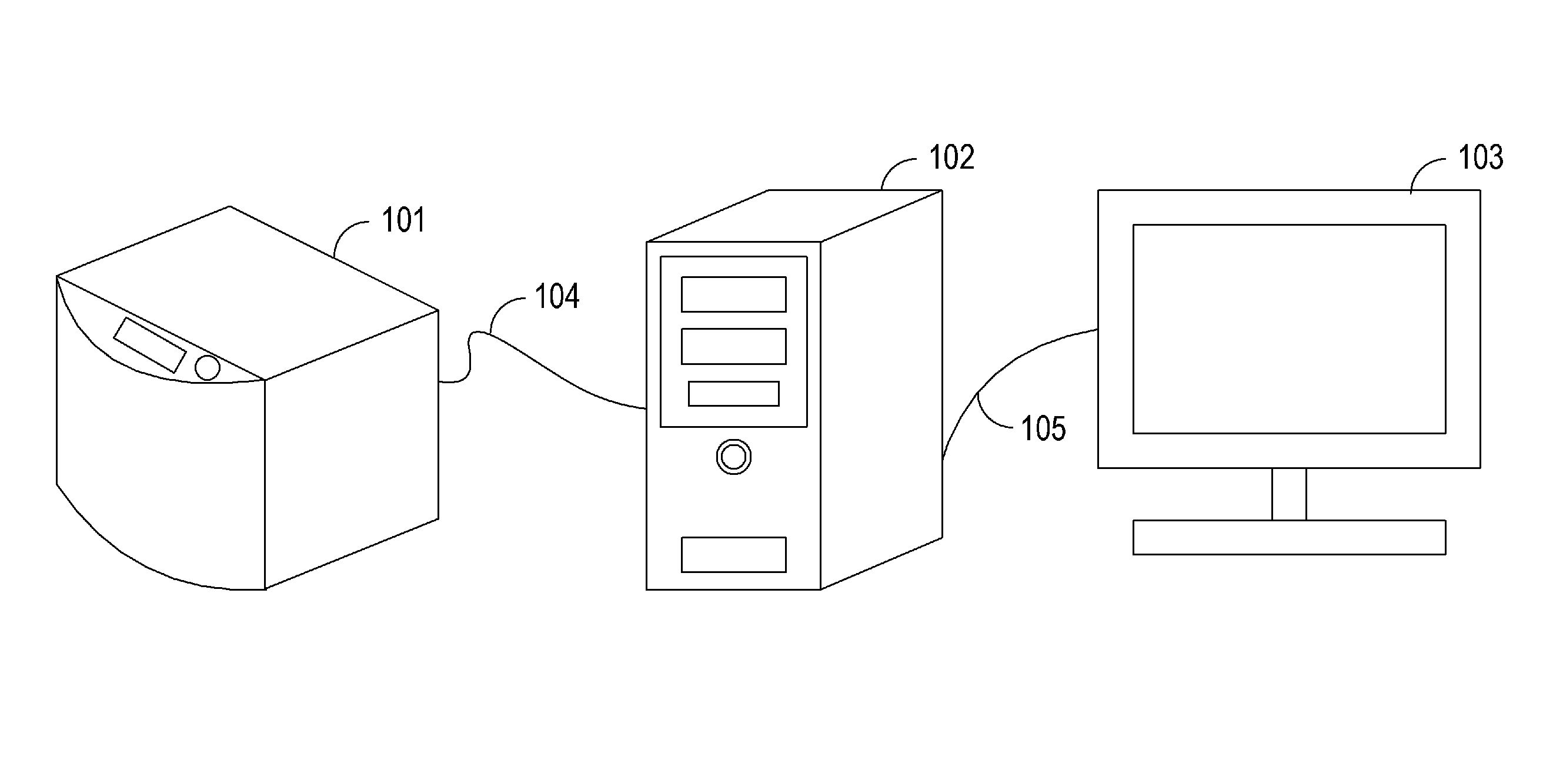
[0028]FIG. 1 is an overall view showing a layout of apparatuses in an imaging system according to a first embodiment of the invention.

[0029]The imaging system according to the first embodiment is composed of an imaging apparatus (microscope apparatus) 101, an image processing apparatus 102, and a display device 103, and is a system with a function to acquire and display a two-dimensional image of a specimen (a test sample) as an object to be imaged. The imaging apparatus 101 and the image processing apparatus 102 are connected to each other with a dedicated or general-purpose I / F cable 104. The image processing apparatus 102 and the display device 103 are connected to each other with a general-purpose I / F cable 105.

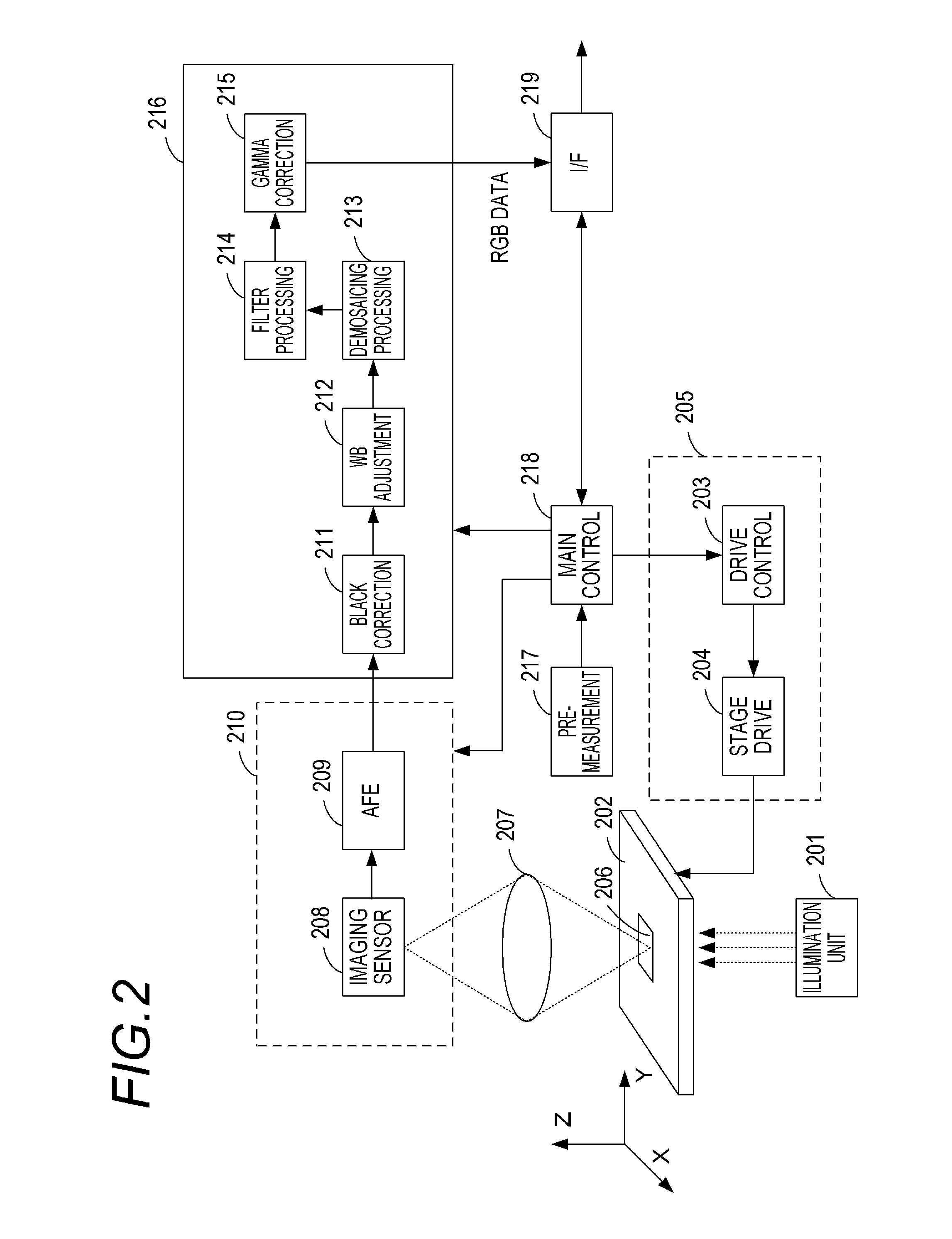
[0030]The imaging apparatus 101 is a virtual slide apparatus having a function of acquiring a plurality of two-dimensional images at different focal positions in an optical axis direction and outputting digital images. The acquisition of the two-dimensional images is done...

second embodiment

[0121]An image processing system according to a second embodiment of the present invention will now be described using the drawings.

[0122]In the first embodiment, an example in which the layer images used to generate the observation image and the analysis image are obtained as required by the imaging apparatus was described. In the second embodiment, an example in which the layer images are obtained in advance and the image processing apparatus obtains required layer images from an image server during image generation will be described. The second embodiment also differs from the first embodiment in that pre-processing relating to image stacking is varied between a cytological diagnosis and a tissue diagnosis. The following description focuses on these differences.

[0123]FIG. 9 is an overall view showing a layout of apparatuses in the image processing system according to the second embodiment.

[0124]The image processing system according to this embodiment includes an image server 1201...

third embodiment

[0134]A third embodiment of the present invention will now be described. In the above embodiments, focus stacking is performed using a select and merge method, but in the third embodiment, focus stacking is implemented using a spatial frequency filtering method in which original images are added together in a spatial frequency region.

[0135]FIG. 11 is a flowchart showing a flow of focus stacking processing. FIG. 11 shows in detail the content of Steps S805 and S810 in FIG. 6 of the first embodiment. In the first embodiment, divided images are selected and merged by comparing contrast values. In this embodiment, processing (also referred to as depth recovery) for enlarging the depth of field by performing image stacking and recovery in a frequency region using a plurality of images will be described.

[0136]In Step S1401, the image processing apparatus 102 obtains a plurality of layer images to be subjected to depth recovery processing.

[0137]In Step S1402, the image processing apparatus...


PUM


Abstract

An image processing apparatus comprises: an image acquisition unit for acquiring a plurality of original images acquired by imaging a specimen including a structure in various focal positions using a microscope apparatus; an image generation unit for generating, on the basis of the plurality of original images, a first image on which blurring of an image of the structure has been reduced in comparison with the original images; and an analysis unit for obtaining information relating to the structure included in the first image by applying image analysis processing to the first image. The image generation unit selects a part of the original images having focal positions included within a smaller depth range than a thickness of the specimen from the plurality of original images obtained from the specimen, and generates the first image using the selected original images.

Description

BACKGROUND OF THE INVENTION[0001]1. Field of the Invention[0002]This invention relates to an image processing apparatus, an imaging system, and an image processing system, and in particular to a technique for assisting observation of an object with the use of a digital image.[0003]2. Description of the Related Art[0004]Recently, a virtual slide system attracts attention in the field of pathology, as a successor to an optical microscope which is currently used as a tool for pathological diagnosis. The virtual slide system enables pathological diagnosis to be performed on a display by imaging a specimen (a sample) to be observed placed on a slide and digitizing the image. The digitization of pathological diagnosis images with the virtual slide system makes it possible to handle conventional optical microscope images of specimens as digital data. It is expected this will bring about various merits, such as more rapid remote diagnosis, provision of information to patients through digita...

Claims


Application Information

Patent Timeline
Patent Type & Authority Applications(United States)
IPC IPC(8): G06K9/40
CPCG06T5/003G06T5/50G06T2207/30024G06T2207/20221G06T2207/10056
Inventor TSUJIMOTO, TAKUYA
Owner CANON KK
Why Eureka
Try Eureka