Method and apparatus for increasing depth of field for an imager

a technology of depth of field and imaging device, which is applied in the direction of image enhancement, camera focusing arrangement, printers, etc., can solve the problems of reducing the brightness of the overall image seen by the sensor, requiring longer image capture times, and still limited depth of field associated with the focus position

Active Publication Date: 2010-05-04
APTINA IMAGING CORP
View PDF8 Cites 58 Cited by
  • Summary
  • Abstract
  • Description
  • Claims
  • Application Information

AI Technical Summary

Problems solved by technology

However, whatever focal position is used to focus on an object, there is still a limited depth of field associated with the focus position.
This reduces the brightness of the overall image seen by a sensor and also requires longer image capture times.

Method used


Image

  • Method and apparatus for increasing depth of field for an imager
  • Method and apparatus for increasing depth of field for an imager
  • Method and apparatus for increasing depth of field for an imager

Examples


Embodiment Construction

[0021]In the following detailed description, reference is made to various specific embodiments in which the invention may be practiced. These embodiments are described with sufficient detail to enable those skilled in the art to practice the invention, and it is to be understood that other embodiments may be employed, and that structural and logical changes may be made without departing from the spirit or scope of the invention.

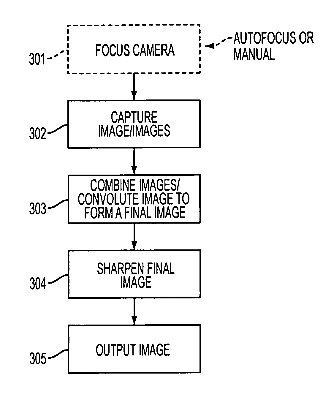
[0022]An imager, e.g., digital camera, constructed in accordance with the invention improves the depth of field of an image by taking multiple exposures (step 302) of an image taken at different relative focus positions. The multiple exposures are then combined to form a single, final image (step 303). It should be appreciated that a camera can be initially focused, either manually or by autofocus on a desired object in the camera view, before the taking of the multiple images (step 301).

[0023]In one embodiment of the invention, N discrete images are captured...


PUM


Abstract

An imaging method and apparatus is disclosed which improves the depth of field of an image by, in one exemplary embodiment, capturing a plurality of images at respective different focus positions, and combines the images into one image and sharpens the one image. In an alternative exemplary embodiment, a single image is captured while the focus positions change during image capture, and the resulting image is sharpened.

Description

FIELD OF THE INVENTION[0001]The invention relates to a method and apparatus for increasing the depth of field for an imaging device, for example a camera.BACKGROUND OF THE INVENTION[0002]In imaging devices, e.g., cameras, there is often a need for a large depth of field. Depth of field is the portion of an image which is “in focus” on either side of an in focus focal point in the image. Objects outside of the depth of field will appear blurry.[0003]Referring to FIG. 1, a digital imager 100, e.g., a digital camera, having a conventional fixed focus lens system is shown in a cross-sectional view. The imager 100 includes a sensor module 170, formed over a substrate 180, which comprises an image sensor 150 having a pixel array and being formed over an attachment layer 160. FIG. 1 schematically shows a fixed focus lens 130 mounted in lens mount 120 in a fixed position over module 170. Incoming light 110 is focused by fixed focus lens 130 onto image sensor 150.[0004]The conventional fixed...

Claims


Application Information

Patent Timeline
Patent Type & Authority Patents(United States)
IPC IPC(8): G03B13/36
CPCG06T5/50H04N5/23212G02B27/0075G06T5/003G02B7/38G06T2207/20221H04N5/23232H04N5/2356H04N23/959H04N23/676H04N23/951H04N23/743
Inventor DALEY, JON
Owner APTINA IMAGING CORP
Why Eureka
Try Eureka