
Lighting device

a technology for lighting devices and light fixtures, which is applied in the direction of lighting and heating equipment, fixed installations, instruments, etc., can solve the problems of increasing total weight, increasing light transmission loss, and additional accuracy problems, so as to reduce light transmission loss, accurate and easy positioning, and lighten the effect of weigh

Inactive Publication Date: 2009-12-01
STANLEY ELECTRIC CO LTD
View PDF7 Cites 62 Cited by
  • Summary
  • Abstract
  • Description
  • Claims
  • Application Information

AI Technical Summary

Benefits of technology

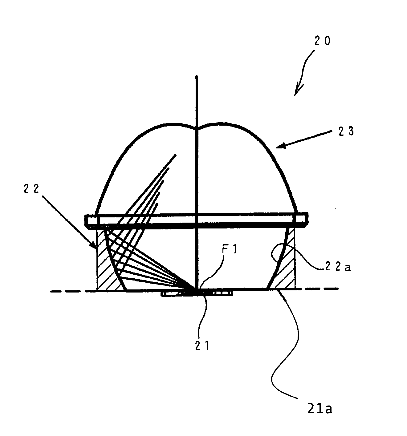
[0017]In view of the foregoing and other problems, desires and needs, an aspect of the invention includes a lighting device that has a simple configuration which can be formed compactly in the direction of its optical axis, that has a comparatively light weight, and that has a functional three-dimensional appearance of innovative design for the sake of enhanced merchantability and novelty.

Problems solved by technology

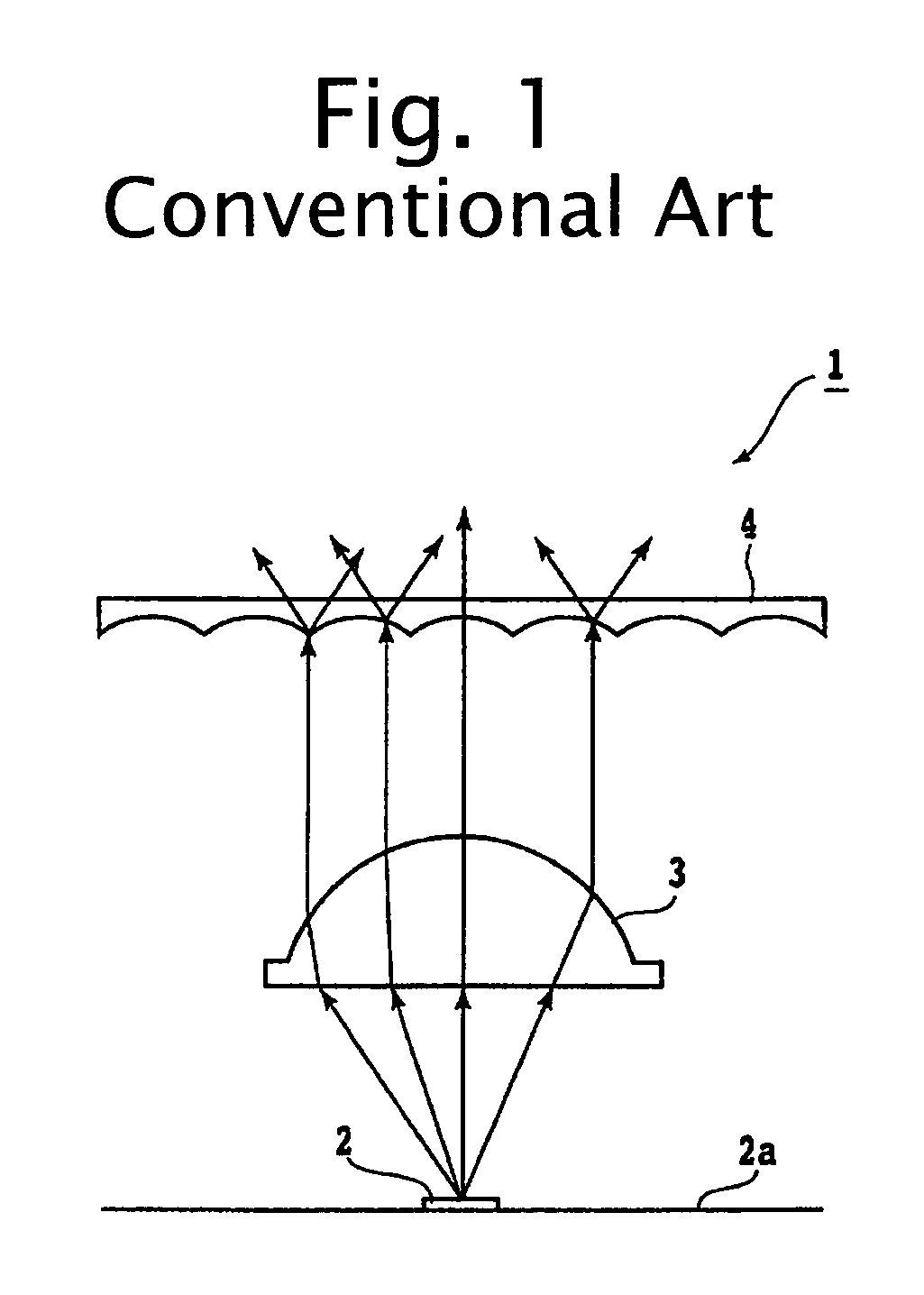
The light transmittances of these optical members thus have an effect on this optical system, increasing the transmission loss of the light.
These optical members can cause additional problems in accuracies, such as a positional accuracy and a tilt accuracy with each other.
In addition, the large dimension in the direction of the optical axis also produces the problem of an increase in total weight.
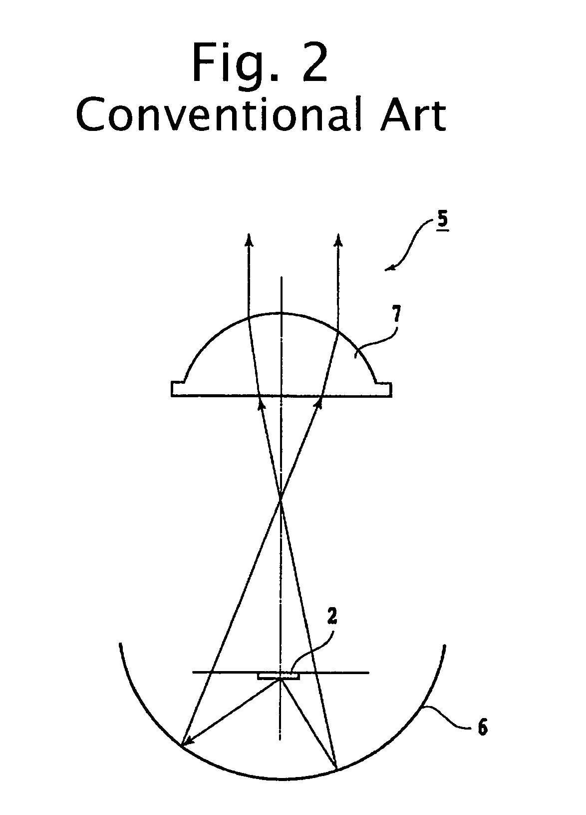
Nevertheless, since the reflecting surface 6 is arranged behind the light source 2, there have also been problems in that the device requires a large dimension in the direction of the optical axis and has an increased total weight.
Since it is difficult and sometimes impossible to provide functional three-dimensional appearances, there have been problems with poor merchantability and design novelty.

Method used


Image

  • Lighting device
  • Lighting device
  • Lighting device

Examples


Embodiment Construction

[0051]Hereinafter, exemplary embodiments of the invention will be described in detail with reference to FIGS. 3 to 13.

[0052]Incidentally, the following embodiments are concrete examples of the invention, and thus include various features that are technically beneficial and / or operable. Nevertheless, the scope of the invention shall not be limited to these aspects.

[0053]FIG. 3 shows the configuration of a lighting device according to an exemplary embodiment of the invention.

[0054]In FIG. 3, the lighting device 10 can include a light source, or a bulb 11, and a projection lens 12 which lies in front of the bulb 11 and focuses light from the bulb 11.

[0055]For example, the bulb 11 may be an incandescent bulb, a halogen lamp, a halogen lamp with an infrared reflecting film, a discharge lamp such as a metal halide lamp, or other light source. The bulb 11 can be fixed, held, and fed by a socket. Incidentally, the lighting device may use an LED for its light source, instead of the bulb 11.

[...


PUM


Abstract

A lighting device can have a simple configuration which can be formed compactly in the direction of its optical axis in particular, and with a light weight. The lighting device can also have a functional, three-dimensional innovative appearance for the sake of enhanced merchantability and novelty. The lighting device can include a light source and a projection lens which is situated so that its source-side focus lies near the light source and its optical axis generally coincides with that of the light source. The projection lens can be a distribution control lens of convex form, having an exit surface shaped aspherically so that the direction of emission is continuously refracted into specified directions with respect to the angle of incidence from the focal position.

Description

[0001]This application claims the priority benefit under 35 U.S.C. §119 of Japanese Patent Application No. 2004-300655 filed on Oct. 14, 2004, which is hereby incorporated in its entirety by reference.BACKGROUND OF THE INVENTION[0002]1. Field of the Invention[0003]The invention relates to a lighting device, and more particularly to automotive / vehicular lighting devices such as headlamps, auxiliary headlamps, and various lamps that are arranged in front parts of a motor vehicle. In addition, the invention relates to illuminating lights for use in lighting fixtures such as traffic lamps, household lamps, general vehicle lamps, etc.[0004]2. Description of the Related Art[0005]FIGS. 1 and 2 show examples of configurations of conventional lighting devices. The lighting device 1 shown in FIG. 1 is composed of a light source 2, a projection lens 3 for focusing the light from the light source 2, and a distribution control member 4 arranged in front of the projection lens 3.[0006]The light s...

Claims


Application Information

Patent Timeline
Patent Type & Authority Patents(United States)
IPC IPC(8): G02B3/02
CPCF21S48/1154F21S48/1159F21S48/1233F21S48/2212F21V5/04F21V13/04F21S48/24F21Y2101/02F21W2131/103F21Y2115/10F21S41/143F21S41/147F21S41/28F21S43/26F21S43/40F21S41/151
Inventor KOIKE, TERUOBAMBA, SHOICHIOWADA, RYOTARO
Owner STANLEY ELECTRIC CO LTD
Learn More