Camera module

a technology of camera module and lens, applied in the field of camera modules, can solve the problems of inability to precisely locate the motor, the telescopic movement of the lens is restricted,

Inactive Publication Date: 2009-12-17
FU ZHUN PRECISION IND SHENZHEN +1
View PDF5 Cites 64 Cited by
  • Summary
  • Abstract
  • Description
  • Claims
  • Application Information

AI Technical Summary

Benefits of technology

[0007]The present invention relates to a camera module. According to an exemplary embodiment of the present invention, the camera module includes a lens mount, a lens unit received in the lens mount, a magnet unit, a printed circuit board-based Rogowski coil and a blade spring. The lens unit includes a lens barrel and a lens received in the lens barrel. The magnet unit includes at least one magnet mounted around the lens unit. The printed circuit board-based Rogowski coil is fixed around the lens barrel. The printed circuit board-based Rogowski coil establishes an induced magnetic field when an electric current is applied thereto. The induced magnetic field of the printed circuit board-

Problems solved by technology

However, the telescopic movement of the lens is confined to directly movement from one fo

Method used


Image

  • Camera module
  • Camera module
  • Camera module

Examples


Embodiment Construction

[0015]Reference will now be made to the drawings to describe the various present embodiments in detail.

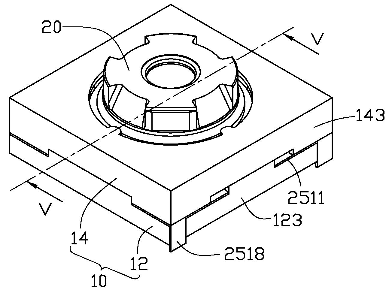
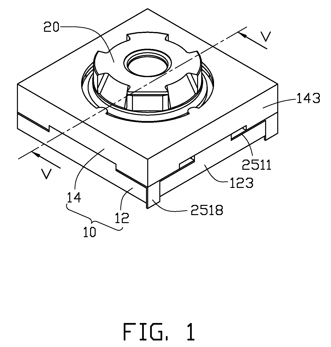
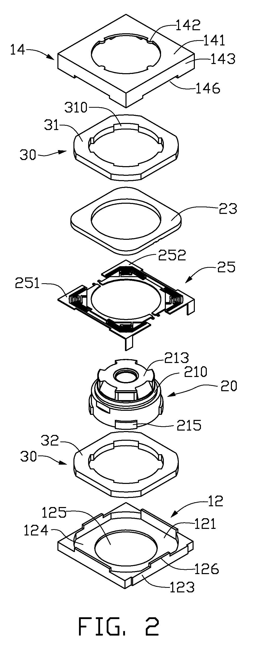
[0016]Referring to FIGS. 1-2, a camera module according to a first exemplary embodiment of the present invention includes a lens mount 10, a lens unit 20, a high precision Rogowski coil 23, a blade spring 25 and a magnet unit 30. The lens unit 20 and the magnet unit 30 are received in the lens mount 10. The magnet unit 30 moves the lens unit 20 telescopically.

[0017]The lens mount 10 includes a base 12 and a cover 14. The base 12 includes a square bottom plate 121 and four sidewalls 123 upwardly and perpendicularly extending from four sides of an outer periphery of the bottom plate 121. The bottom plate 121 defines a central hole 125 in a central portion thereof. The bottom plate 121 and the sidewalls 123 cooperatively define a receiving space 124 therein. The receiving space 124 has a substantially rectangular shape with four curved corners. Four locking walls 126 upwardly and perp...


PUM


Abstract

An exemplary camera module includes a lens mount, a lens unit, a magnet unit, a printed circuit board (PCB)-based Rogowski coil and a blade spring. The PCB-based Rogowski coil is fixed around the lens unit. The PCB-based Rogowski coil establishes an induced magnetic field when an electric current is applied thereto. The induced magnetic field interacts with the magnet unit to generate a magnetic force moving the lens unit telescopically. The blade spring includes a plurality of ribs. Each rib includes a moveable end connected with the lens unit and an opposite fixed end. The moveable end moves together with the lens unit with respect to the fixed end to cause the ribs to distort and generate an elastic force. The lens unit stops at a focal position when the magnetic force and the elastic force come to a balance.

Description

BACKGROUND[0001]1. Technical Field[0002]The present invention relates to cameras, and particularly to a camera module for use in a digital camera, a portable electronic apparatus such as a mobile telephone, a personal digital assistant or other device.[0003]2. Description of Related Art[0004]Camera modules are generally installed in mobile telephones, personal digital assistants or other portable electronic apparatuses due to their convenience and practicality. As design of the camera modules has evolved toward light weight and compactness, so have the currently popular digital camera modules.[0005]Conventionally, a two-step camera module is utilized. The camera module generally includes a lens and a motor driving the lens in telescopic operation. When the camera module operates, the lens is driven by the motor to move from a near focal point to a far focal point, or vice versa.[0006]However, the telescopic movement of the lens is confined to directly movement from one focal point t...

Claims


Application Information

Patent Timeline
IPC IPC(8): G03B17/00G02B7/04G03B3/10G03B13/34G03B17/02H04N5/225H04N5/232H04N5/335
CPCH01F7/16G02B7/08H01F7/122H01F7/066G02B13/0025
Inventor SHIH, WUN-CHANGHUANG, CHING-HSINGWENG, CHENG-FAWANG, JEN-TEYOU, HUAI-CHAOWEN, DA-YIWANG, BIAOHU, YUN-MING
Owner FU ZHUN PRECISION IND SHENZHEN
Why Eureka
Try Eureka