Confocal scanning microscope

a scanning microscope and optical technology, applied in the field of optical scanning microscopes, can solve the problems of difficult three-dimensional observation of fluorescent specimens and inability to obtain fluorescent images in the desired condition

Active Publication Date: 2005-06-09
EVIDENT CORP
View PDF3 Cites 66 Cited by
  • Summary
  • Abstract
  • Description
  • Claims
  • Application Information

AI Technical Summary

Benefits of technology

[0008] According to the confocal scanning microscope of the present invention, a confocal scanning microscope that irradiates a specimen with a stimulating light beam that causes optical chemical change to the specimen, focuses an exciting light beam to an exciting light beam focal point so as to irradiate the specimen with the exciting light beam, and scans the exciting light beam at least in a plane perpendicular to a depth direction, thereby allowing observation of fluorescence which also indicates the influence of the stimulating light beam, includes a stimulating light beam scanning unit that scans at least a predetermined plane perpendicular to the depth direction of the stimulating light beam focal position, a stimulating light beam scanning control unit that controls the scanning area of the stimulating light beam to a desired area, an exciting light beam scanning control unit that controls the scanning area of the exciting light beam to a desired area, an exciting light beam focal position changing unit, provided in an excitation fluorescence optical path, which is a portion of an optical path where the exciting light beam and the fluorescence pass and located outside a common optical path where the exciting light beam, the fluorescence, and the stimulating light beam pass, that changes at least the exciting light beam focal position in the depth direction, and an exciting light beam control unit that controls the exciting light beam focal position variably to a desired position.

Problems solved by technology

Thus, it may be difficult to observe the fluorescent specimen three-dimensionally while providing the light stimulus continuously or repeatedly by the stimulating laser beam to an area including an optional point in the specimen.
Hence, there may be a problem that the advantage of a confocal scanning microscope that the three-dimensional fluorescence observation is possible by the confocal effect in combination with a light stimulus, can not be exerted, thus a fluorescent image cannot be obtained in a desired condition.

Method used


Image

  • Confocal scanning microscope
  • Confocal scanning microscope
  • Confocal scanning microscope

Examples


first embodiment

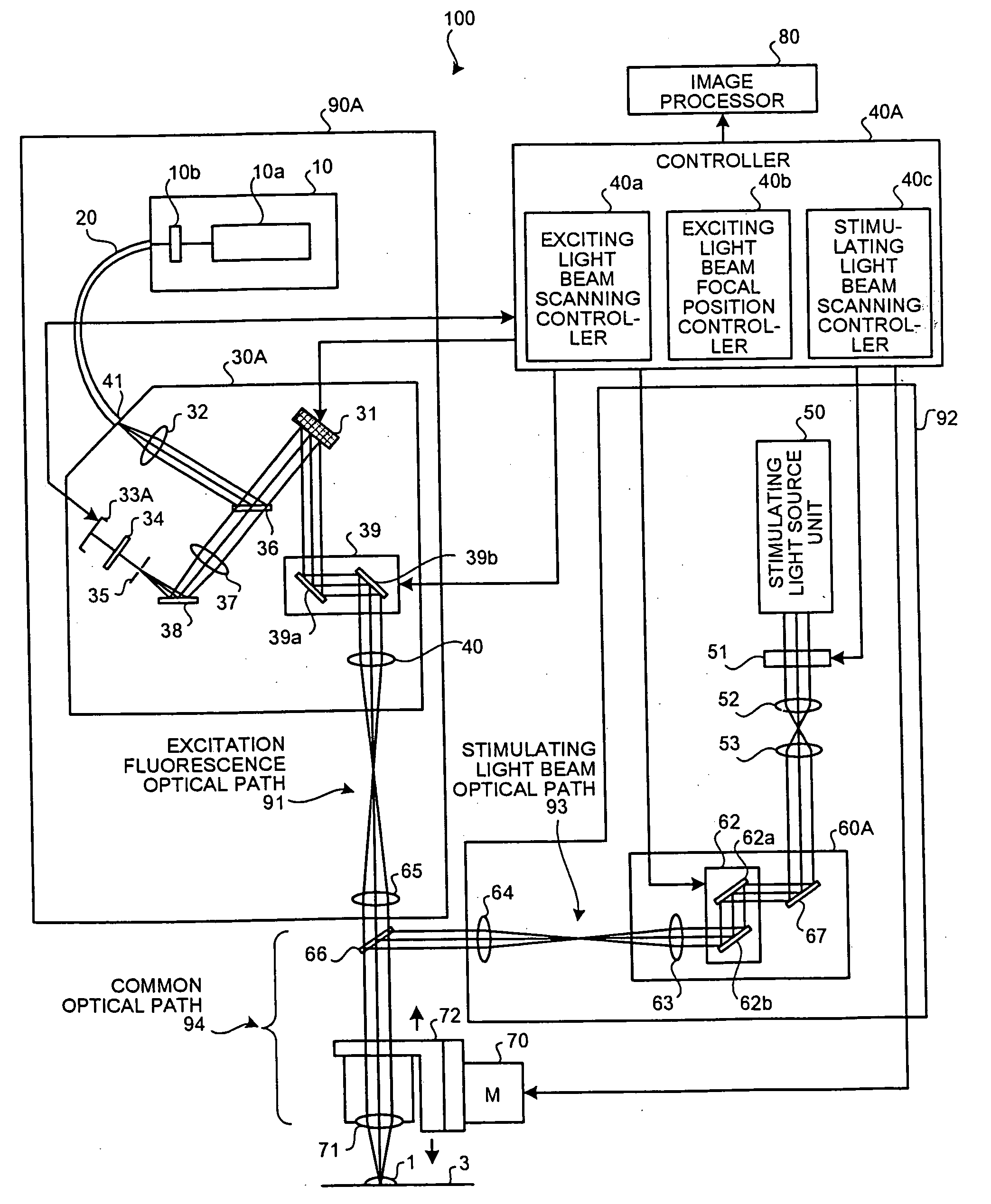
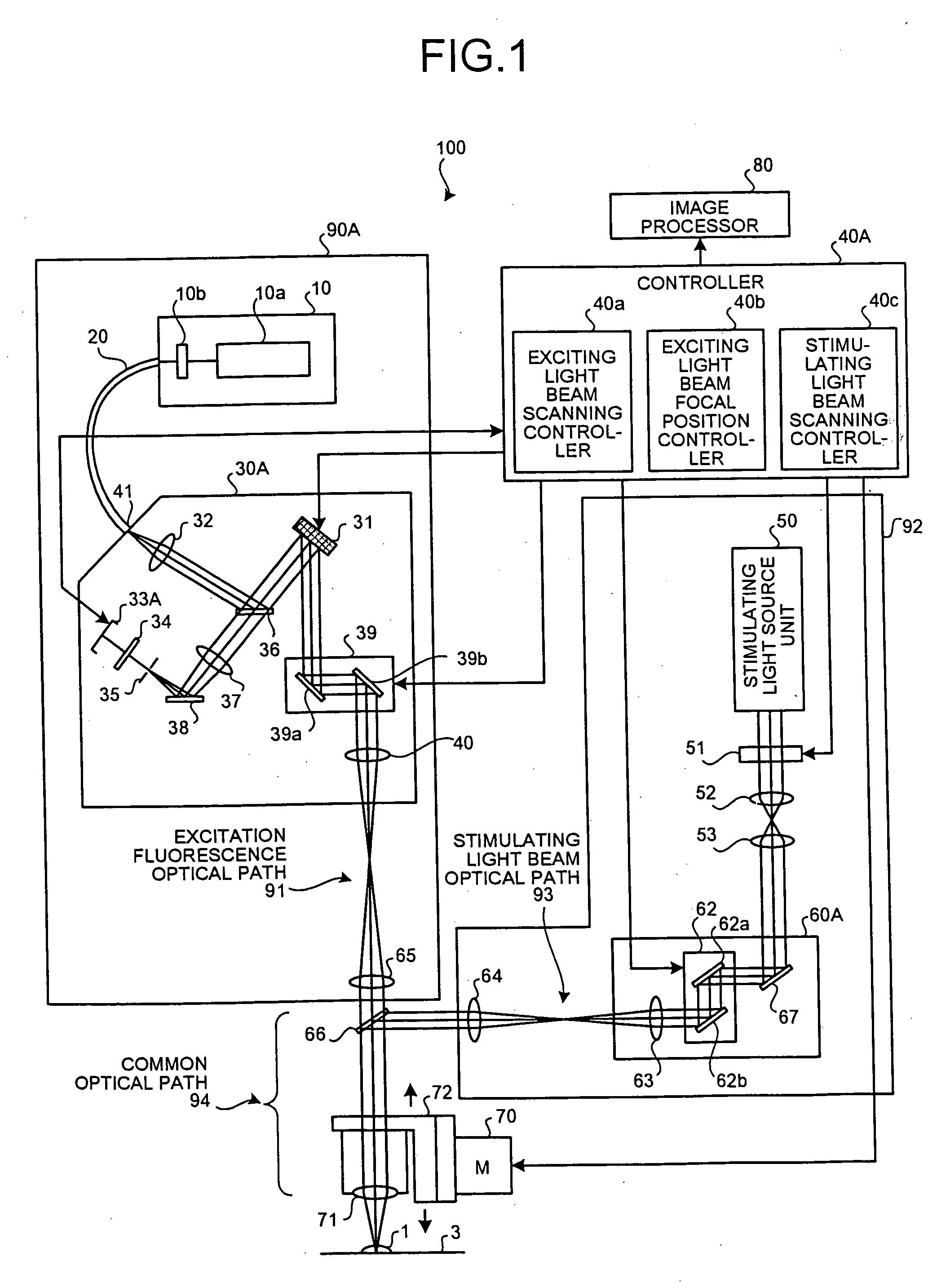
[0021]FIG. 1 is a block diagram of a schematic configuration of a confocal scanning microscope 100 of the The confocal scanning microscope 100 includes an exciting light beam irradiating unit 90A that controls an exciting light beam and a fluorescence, a stimulating light beam irradiating unit 92 that controls a stimulating light beam, and a controller 40A that controls the exciting light beam irradiating unit 90A and the stimulating light beam irradiating unit 92. The confocal scanning microscope 100 further includes, in a common optical path 94 provided commonly for an excitation fluorescence optical path 91 for the passage of an exciting light beam and a fluorescence and a stimulating light beam optical path 93 for the passage of a stimulating light beam, a combining dichroic mirror 66, an objective lens 71, a guide driving mechanism 72 that supports the objective lens 71, a motor 70 that drives the guide driving mechanism 72, a specimen 1 as the observation subject, and a speci...

second embodiment

[0042]FIG. 9 is a block diagram of a schematic configuration of a confocal scanning microscope 120 as the present invention. A stimulating light beam scanning unit 60B includes mirrors 67 and 68, the deformable mirror 31B, the galvano mirror unit 62, and the pupil projecting lens 63. Moreover, a controller 40C includes the exciting light beam scanning controller 40a, the exciting light beam focal position controller 40b, the stimulating light beam scanning controller 40c, and a stimulating light beam focal position controller 40d. The same reference characters are applied to the same elements as in FIG. 1.

[0043] The exciting light beam scanning controller 40a controls the scanning of the exciting light beam scanning plane 2 by controlling the galvano mirror unit 39, whereas the exciting light beam focal position controller 40b controls the position in the depth direction of the focal point of the exciting light beam by controlling the deformable mirror 31. The stimulating light beam...


PUM

PropertyMeasurementUnit
wavelengthaaaaaaaaaa

Abstract

A confocal scanning microscope includes a stimulating light beam scanning unit that scans at least a predetermined plane perpendicular to the depth direction of the stimulating light beam focal position, a stimulating light beam scanning control unit that controls the scanning area of the stimulating light beam to a desired area, an exciting light beam scanning control unit that controls the scanning area of the exciting light beam to a desired area, an exciting light beam focal position changing unit, provided in an excitation fluorescence optical path, which is a portion of an optical path where the exciting light beam and the fluorescence pass and located outside a common optical path where the exciting light beam, the fluorescence, and the stimulating light beam pass, that changes at least the exciting light beam focal position in the depth direction, and an exciting light beam control unit that controls the exciting light beam focal position variably to a desired position.

Description

CROSS-REFERENCE TO RELATED APPLICATION [0001] This application is based upon and claims benefit of priority from the prior Japanese Patent Application No. 2003-407666, filed on 2003, Dec. 5th; the entire content of which is incorporated herein by reference. BACKGROUND OF THE INVENTION [0002] 1) Field of the Invention [0003] The present invention relates to a confocal scanning microscope that irradiates a fluorescent-dyed specimen with stimulating light and detect fluorescence emitted from the specimen for observation of spatial fluorescence distribution and influence of the stimulating light. [0004] 2) Description of the Related Art [0005] It is known that confocal scanning microscopes that employ a stimulating laser to stimulate a specimen are effectively used in the caged method, Fluorescence Loss in Photobleaching (FLIP), or the like. According to the caged method, a caged reagent and a fluorescence indicator, which is calcium sensitive to indicate the calcium ion concentration, ...

Claims


Application Information

Patent Timeline
Patent Type & Authority Applications(United States)
IPC IPC(8): G01N21/64G02B21/00
CPCG02B21/0044G02B21/0048G02B2207/114G02B21/0076G02B21/32G02B21/006
Inventor SASAKI, HIROSHI
Owner EVIDENT CORP
Why Eureka
Try Eureka