
Double confocal scanning microscope

a scanning microscope and double confocal technology, applied in the field of double confocal scanning microscopes, can solve the problem that the axial resolution that is experimentally achievable with a generic double confocal scanning microscope is less than the theoretically possible axial resolution

Inactive Publication Date: 2006-05-30
LEICA MICROSYSTEMS CMS GMBH
View PDF6 Cites 6 Cited by
  • Summary
  • Abstract
  • Description
  • Claims
  • Application Information

AI Technical Summary

Benefits of technology

[0004]It is therefore the object of the present invention to describe a double confocal scanning microscope with which, especially in

Problems solved by technology

Especially in the context of multi-color fluorescence applications, however, the axial resolution that is experimentally achievable with a generic double confocal scanning microscope is hitherto less than the theoretically possible axial resolution.

Method used


Image

  • Double confocal scanning microscope
  • Double confocal scanning microscope
  • Double confocal scanning microscope

Examples


Embodiment Construction

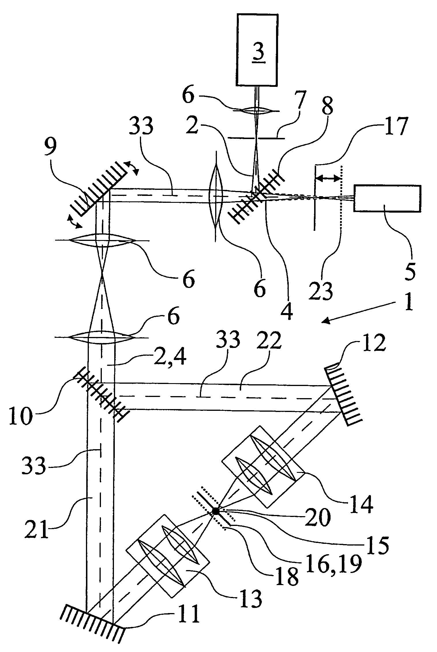
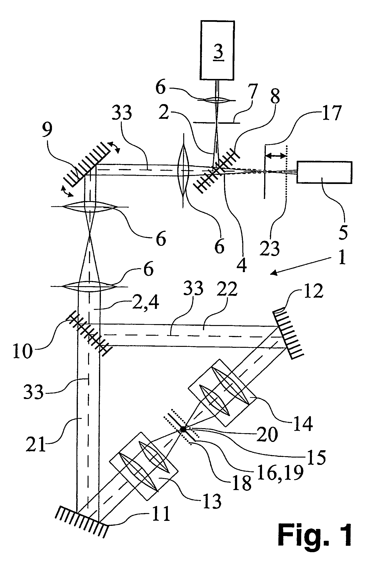
[0009]Coordination of the accumulated aberrations is accomplished in this context with respect to the optical axis and / or with respect to at least one surface in the specimen region. In terms of coordination of the accumulated aberrations with respect to the optical axis, provision is made for a lateral error correction, preferably in rotationally symmetrical fashion; in terms of coordination of the accumulated aberrations with respect to at least one surface in the specimen region, an axial error correction is preferably provided for.

In very general terms, the surface in the specimen region is a calculated reference magnitude. The surface can have any desired shape and location, for example a slightly curved surface of a spherical segment, of an ellipsoid, of a paraboloid, or of a hyperbolic paraboloid. The surface could also be a plane. The surface could be oriented symmetrically with respect to a straight line lying in the focal plane or with respect to the optical axis. Differen...


PUM


Abstract

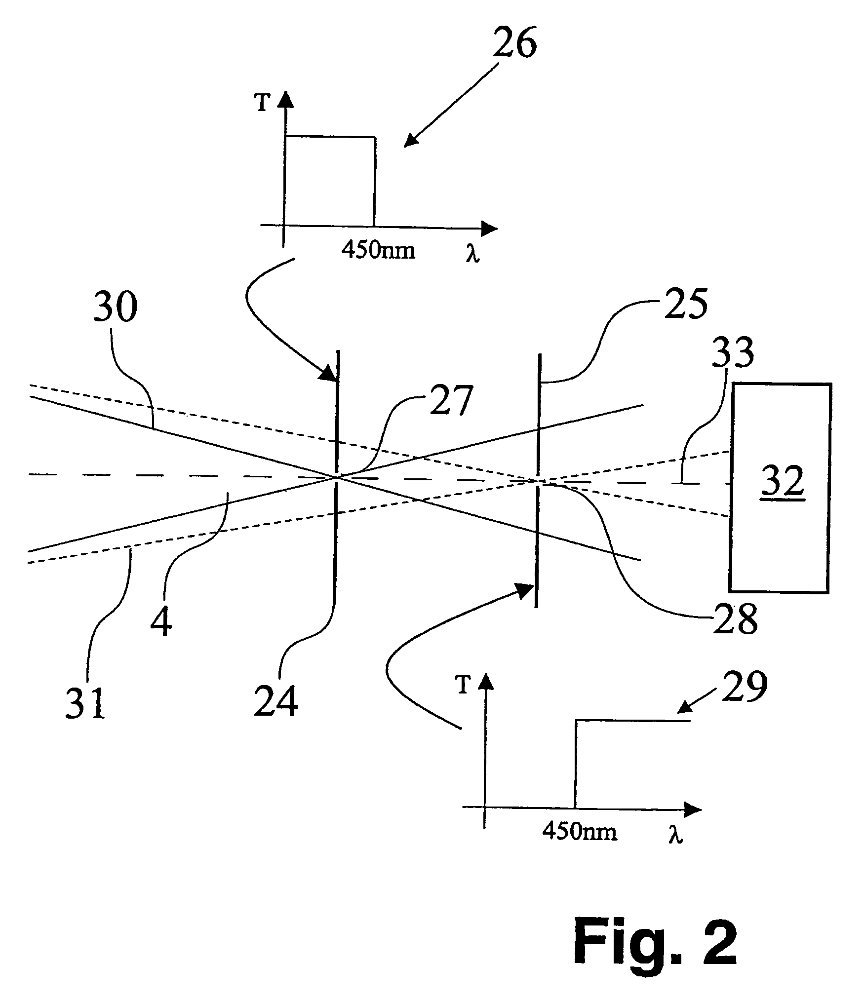
The present invention concerns a double confocal scanning microscope (1) having an illuminating beam path (2) of at least one light source (3), and a detected beam path (4) of at least one detector (5), and in order to achieve almost the theoretically possible resolution capability, in particular in the context of multi-color fluorescence applications, is characterized in that the optical properties in particular of the components (6, 10, 13, 14) arranged in the beam path are coordinated with one another in such a way that the accumulated aberrations, with respect to the optical axis (33) and / or at least one surface (18, 19, 20) in the specimen region, are at least of the order of magnitude of the theoretically achievable resolution capability.

Description

CROSS REFERENCE TO RELATED APPLICATIONS[0001]This invention claims priority of a German filed patent application DE 100 18 256.9 which is incorporated by reference herein.FIELD OF THE INVENTION[0002]The present invention concerns a double confocal scanning microscope having at least one light source defining an illuminating beam path and at least one detector defining detection beam path.BACKGROUND OF THE INVENTION[0003]Double confocal scanning microscopes are known from EP 0 491 289. In double confocal scanning microscopy, light from a light source is divided into two partial beams, each partial beam being focused by way of an objective onto a common specimen point. The two objectives are arranged on different sides of the specimen plane that is common to them. At the specimen point or the detection pinhole, the interferometric illumination causes the formation of an interference pattern that, in the context of constructive interference, exhibits a principal maximum and several sec...

Claims


Application Information

Patent Timeline
IPC IPC(8): G02B21/06G02B21/00G01N21/64
CPCG02B21/0032G02B21/0076G02B21/0072G02B21/0056
Inventor ENGELHARDT, JOHANNBEWERSDORF, JORGGUGEL, HILMARHOFFMANN, JUERGEN
Owner LEICA MICROSYSTEMS CMS GMBH
Learn More