Far-infrared detector spectral response measuring system in confocal microscopy

An infrared detector and measurement system technology, applied in the field of infrared detection, can solve the problems of great difficulty, difficulty in obtaining high-power mid- and far-infrared light irradiation, and difficult alignment of infrared optical systems.

Inactive Publication Date: 2008-06-25
INST OF SEMICONDUCTORS - CHINESE ACAD OF SCI
View PDF0 Cites 6 Cited by
  • Summary
  • Abstract
  • Description
  • Claims
  • Application Information

AI Technical Summary

Problems solved by technology

[0005] However, due to the invisibility of infrared light, especially in the mid-to-far infrared band, people have encountered some difficulties in the measurement of the spectral response performance parameters of mid-to-far infrared detectors, especially in the measurement system of mid-to-far infrared detector spectral response performance parameters. The optical system cannot accurately measure the infrared spot, and the infrared optical system is not easy to align, especially for the research of the mid-to-far infrared detection device with a small response area, it is even more difficult
In addition, due to the lack of light sources with high power output in such a large mid-to-far infrared spectral range among all kinds of mid-to-far infrared light sources, it is difficult for researchers to obtain high-power mid-to-far infrared light irradiation on samples with small response areas.
Therefore, the spectral response performance test of the new mid-to-far infrared detector, which is in the initial research stage, has encountered great difficulties.

Method used


Image

  • Far-infrared detector spectral response measuring system in confocal microscopy
  • Far-infrared detector spectral response measuring system in confocal microscopy

Examples


Embodiment Construction

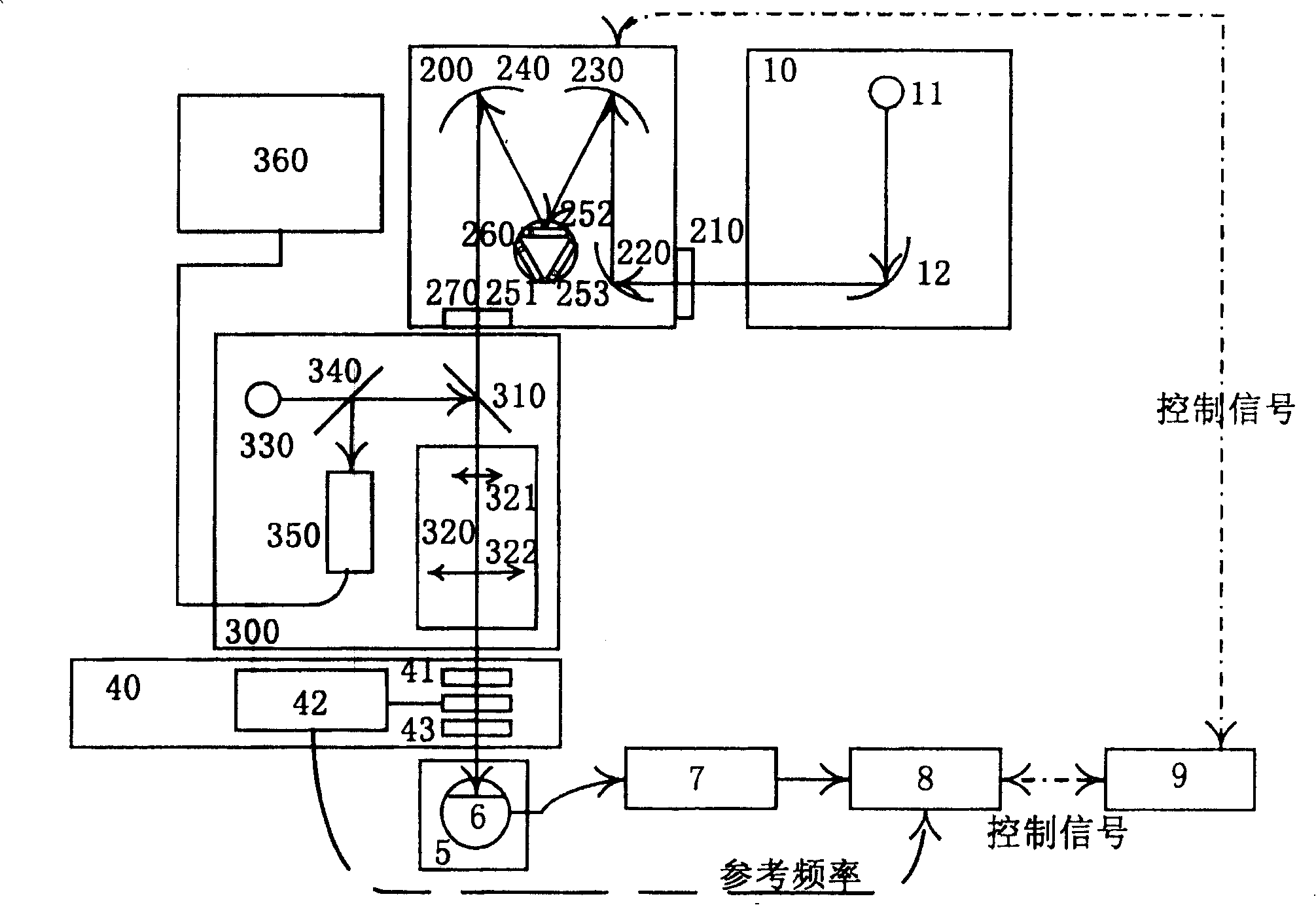
[0041] see figure 1 Shown, a kind of confocal microscope mid-far infrared detector spectral response measurement system of the present invention, this measurement system comprises:

[0042] An infrared light source 10, the infrared light source system 10 includes: an infrared light source 11 and a gold-plated concave reflector 12, the concave reflector 12 is located on the outgoing light path of the infrared light source 11;

[0043] An infrared monochromator 200, the input end of the infrared monochromator 200 is connected with the output end of the infrared light source 10 to play an infrared spectroscopic effect, and the infrared monochromator 200 includes:

[0044] a first incident slit 210;

[0045] A concave reflector 220 of a first gold-coated film receives the reflected light of the concave reflector 12 of the gold-plated film of the infrared light source system 10, and the reflected light of the concave reflector 12 of the gold-plated film passes through the first in...


PUM


Abstract

The invention provides a confocal microscopy mid and far-infrared spectral response measurement system, which comprises an infrared source; an input end of an infrared monochrometer is connected to an output end of the infrared source; an infrared confocal microscopic system is arranged on an output light path of the infrared monochrometer; a chopper light limiting unit is arranged between the infrared confocal microscopic system and a three-dimensional micro-displacement platform and arranged on the output light path of the infrared monochrometer; the three-dimensional micro-displacement platform is arranged on the output light path of the infrared monochrometer; a sample refrigeration Dewar is fixed on the three-dimensional micro-displacement platform; a preamplifier is connected with the sample refrigeration Dewar, which plays a role of amplifying the sample electric signals; a phase-locked amplifier is connected with the preamplifier; a controlling computer is connected with the phase-locked amplifier and the infrared monochrometer to control the course of the test implemented by the phase-locked amplifier and the infrared monochrometer and collects the data signal inputted by the phase-locked amplifier and the infrared monochrometer at the same time.

Description

technical field [0001] The invention relates to the technical field of infrared detection, in particular to a spectral response measurement system of a confocal microscope mid-far infrared detector. Background technique [0002] In the electromagnetic spectrum, the experimentally meaningful frequency (or wavelength) range includes more than 20 orders of magnitude. For convenience, an octave scale is often used to characterize the frequency or wavelength range under study. The visible spectrum with wavelengths between 0.38-0.75 microns spans only one octave, while the infrared band spans about 10 octaves. Therefore, no matter from the perspective of scientific research or technical application, the infrared spectral region has richer content and greater development potential than the visible spectral region. [0003] So far, infrared has been increasingly used in the fields of modern military technology, industrial and agricultural production, space technology, resource exp...

Claims


Application Information

Patent Timeline
Patent Type & Authority Applications(China)
IPC IPC(8): G01J3/00G01J3/02G01J3/10G01J3/12G01J3/18G01J3/26G01J3/28G01S7/497G01S17/88G01S17/89G01S17/95
Inventor 朱汇郑厚植谭平恒章昊甘华东孙晓明李桂荣
Owner INST OF SEMICONDUCTORS - CHINESE ACAD OF SCI
Why Eureka
Try Eureka