
Balanced charge waveform for transcutaneous pacing

a charge waveform and charge waveform technology, applied in electrotherapy, heart stimulators, therapy, etc., can solve the problems of long-term transcutaneous pacing, high impedance of the electrode, and decrease the conductivity between the electrode and the patient, so as to minimize the hydrolysis of the electrode gel

Active Publication Date: 2011-09-27
PHYSIO CONTROL INC
View PDF27 Cites 1 Cited by
  • Summary
  • Abstract
  • Description
  • Claims
  • Application Information

AI Technical Summary

Benefits of technology

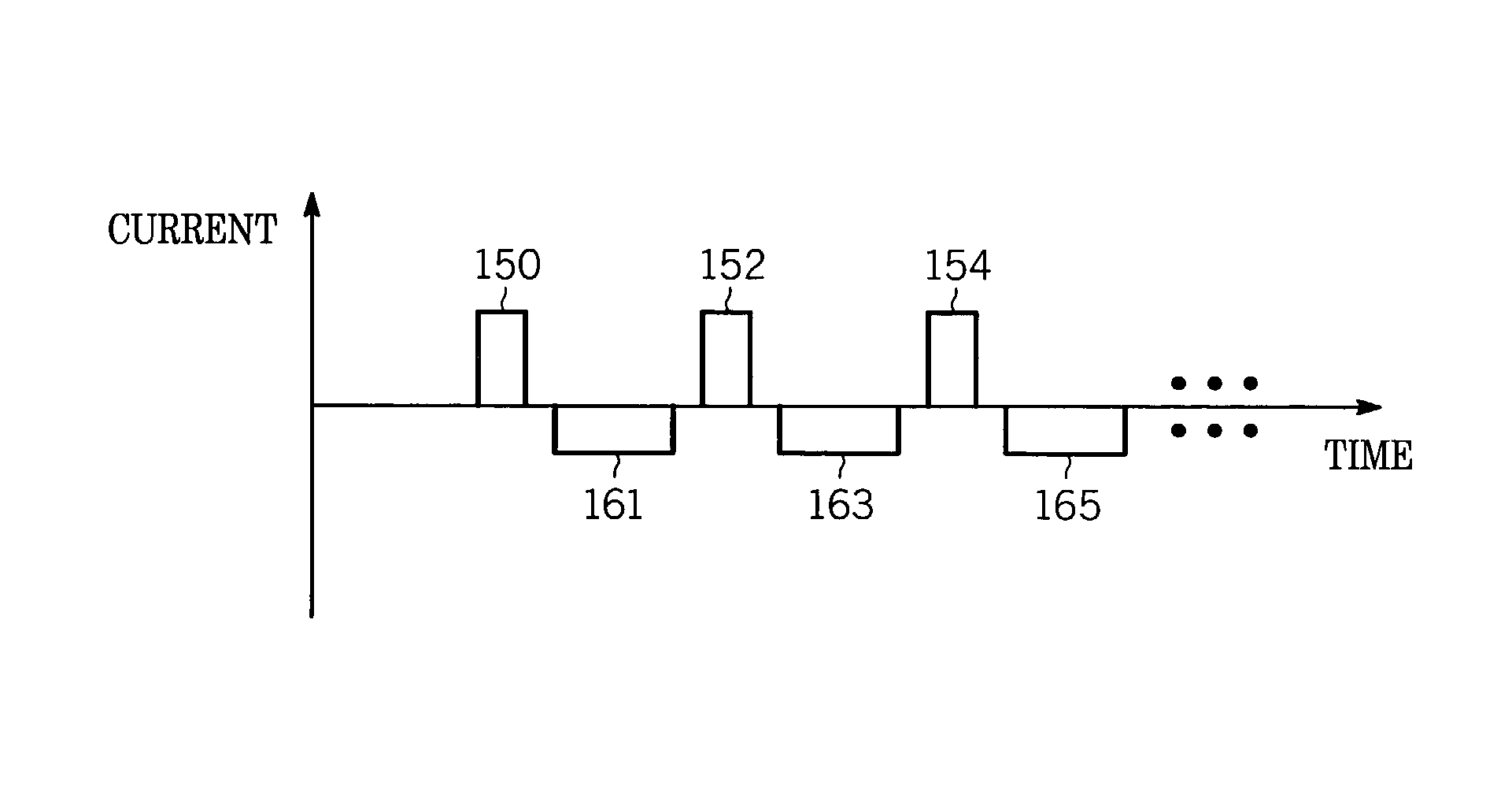
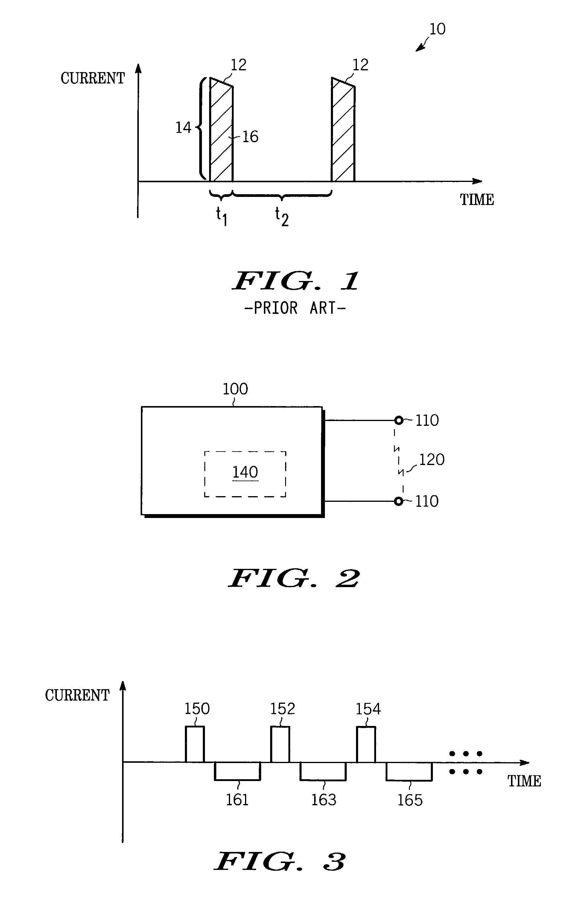
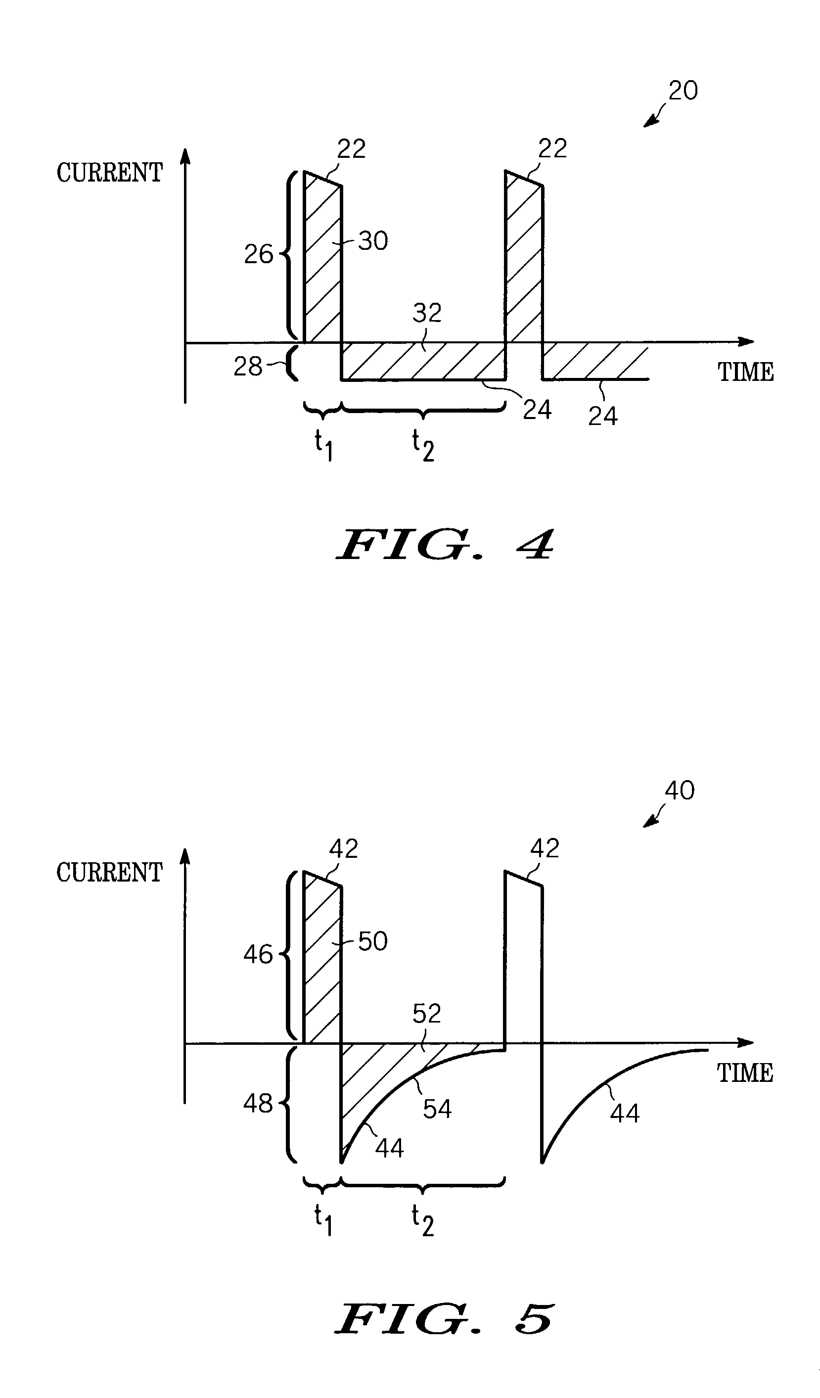
[0010]The invention overcomes the problem of the prior art. The invention provides external pacemaker systems and methods that deliver pacing waveforms that alleviate the problem of the prior art, by minimizing the hydrolysis of the electrode gel, and thus prevent the resulting harmful effects.
[0012]Accordingly, the invention generates pacing waveforms that maintain a balanced charge in the electrodes. This minimizes the hydrolysis of the electrode gel during long term transcutaneous pacing. The invention thus allows long-term transcutaneous pacing without fear that the pacing will be stopped due to excessive electrode impedance. In addition, the invention allows the devices, methods, and waveforms of the invention to be applied using conventional electrodes.

Problems solved by technology

A problem arises when such transcutaneous pacing is long-term.
The hydrogen and oxygen gas, which tend to accumulate between the patient's skin and the flexible conductive plate, and produces two primary undesirable effects.
First, the accumulation of the gases generally decreases the conductivity between the electrode and the patient.
Generally, the impedance of the electrodes may reach such a high value that the pacer is unable to generate a sufficient voltage to apply a pacing pulse.
Second, the gas has a tendency to accumulate in pockets, causing the current density in areas of the electrode to increase.
If the density of current flow increases in the areas remaining in contact with the patient, patient discomfort may result.
If the current density increases even further, burning of the patient's skin may result.
The increasing current density problem is exacerbated with electrodes designed for pediatric use.
For children or patients with sensitive skin, the change in electrode pH can become highly irritating to the dermic layer.
While the accumulation of hydrogen and oxygen in the electrodes may be prevented by appropriately constructing the electrodes, such a solution is only applicable in limited circumstances.

Method used


Image

  • Balanced charge waveform for transcutaneous pacing
  • Balanced charge waveform for transcutaneous pacing
  • Balanced charge waveform for transcutaneous pacing

Examples


Embodiment Construction

[0020]The following detailed description is merely exemplary in nature and is not intended to limit the invention or the application and uses of the invention. Furthermore, there is no intention to be bound by any expressed or implied theory presented in the preceding technical field, background, brief summary or the following detailed description. As has been mentioned, the invention provides external pacemaker systems and methods that deliver charge-balanced pacing waveforms that alleviate the problems arising from the hydrolysis of the electrode gel. The invention is now described in more detail.

[0021]FIG. 2 is a block diagram of a transcutaneous pacing system 100 according to the invention. System 100 is made as is known in the art. System 100 may be implemented alone, or in conjunction with other systems, such as defibrillation systems, etc. System 100 may be part of what would be used by trained medical personnel, or untrained users in a home or public access situation, or par...


PUM


Abstract

External pacemaker systems and methods deliver pacing waveforms that minimize hydrolysis of the electrode gel. Compensating pulses are interleaved with the pacing pulses, with a polarity and duration that balance the net charge at the electrode locations. The compensating pulses are preferably rectangular for continuous pacing, and decay individually for on-demand pacing.

Description

TECHNICAL FIELD[0001]The present invention relates generally to medical pacemaker systems, and more particularly to devices and methods that generate pacing waveforms for minimizing patient skin burns during long-term transcutaneous defibrillation.BACKGROUND[0002]Systems are made for administering to patients pacing pulses externally. Advantageously, external defibrillators may also administer such external pacing. A common electrode used to connect a heart pacer to a patient incorporates an electrically conductive, impedance-decreasing gel disposed between a flexible conductive plate and the patient's skin. The gel ensures good electrical contact between the patient and the conductive plate, and adheres the electrode to the patient's skin. During pacing, pulses are generated by the heart pacer and applied through the electrodes and into the patient. Typical pacing equipment will commonly deliver a pacing pulse having an amplitude of up to 300 volts, and a maximum current of about 0...

Claims


Application Information

Patent Timeline
IPC IPC(8): A61N1/362
CPCA61N1/3625
Inventor SULLIVAN, JOSEPH L.
Owner PHYSIO CONTROL INC
Learn More