Automotive door handle assembly with directly coupled-inertia activated mechanism

a technology of automotive vehicles and door handles, applied in the direction of mechanical devices, carpet fasteners, lock applications, etc., can solve the problems of occupants being exposed to a greater risk of being expelled from the vehicle, the handle moving inadvertently to the unlatched position, and the crash accident of the vehicl

Active Publication Date: 2011-10-04
YANG LEI
View PDF13 Cites 34 Cited by
  • Summary
  • Abstract
  • Description
  • Claims
  • Application Information

AI Technical Summary

Benefits of technology

[0006]The present invention is directed to a mechanism that counteracts inertia forces caused by a vehicle crash. The mechanism of the invention is also called directly coupled-inertia activated mechanism and may be incorporated into a door handle assembly of a vehicle. With one aspect of the invention, the directly coupled-inertia activated mechanism of the invention will compensate the inertia force on the door handle assembly, thus prevent the door handle assembly from unlatching the latch mechanism during a side crash. After the crash or when the crash force is removed, the directly coupled-inertia activated mechanism of the invention will allow the door handle assembly to function normally, thereby permitting the door to be opened and the occupants to exit from the vehicle.

Problems solved by technology

Automotive vehicles can be involved in crash accident.
In particular side crash can cause the handle to move inadvertently to unlatched position.
Doors are unlatched and swung open, thus occupants are exposed to greater risk of being expelled from the vehicles.
Very often, side crash is very severe that acceleration can be as high as 200 G in a very short of time interval.
However, when the acceleration of the side crash is very high, e.g. 200 G, counterweight of suitable size fit into current automotive doors can not stop the handle from inadvertent move.
However, it is highly possible and often the case that the handle already moves out passing a threshold and cause the latch to unlatch the door before this particular component begin to move as to block the handle's inadvertent movement.
The sudden block / stop induces very high stress on the blocking component and the one to be blocked, such that fatigue develops over the time.

Method used


Image

  • Automotive door handle assembly with directly coupled-inertia activated mechanism
  • Automotive door handle assembly with directly coupled-inertia activated mechanism
  • Automotive door handle assembly with directly coupled-inertia activated mechanism

Examples


Embodiment Construction

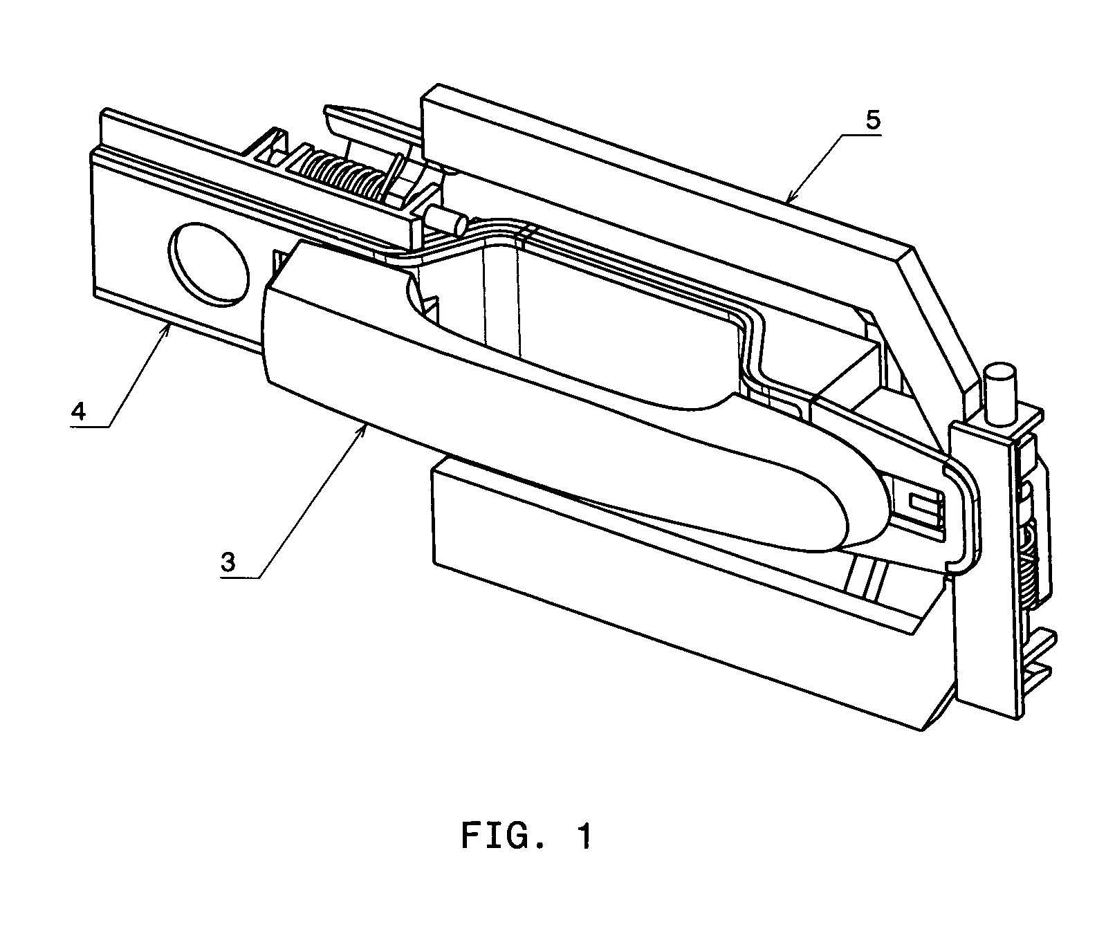
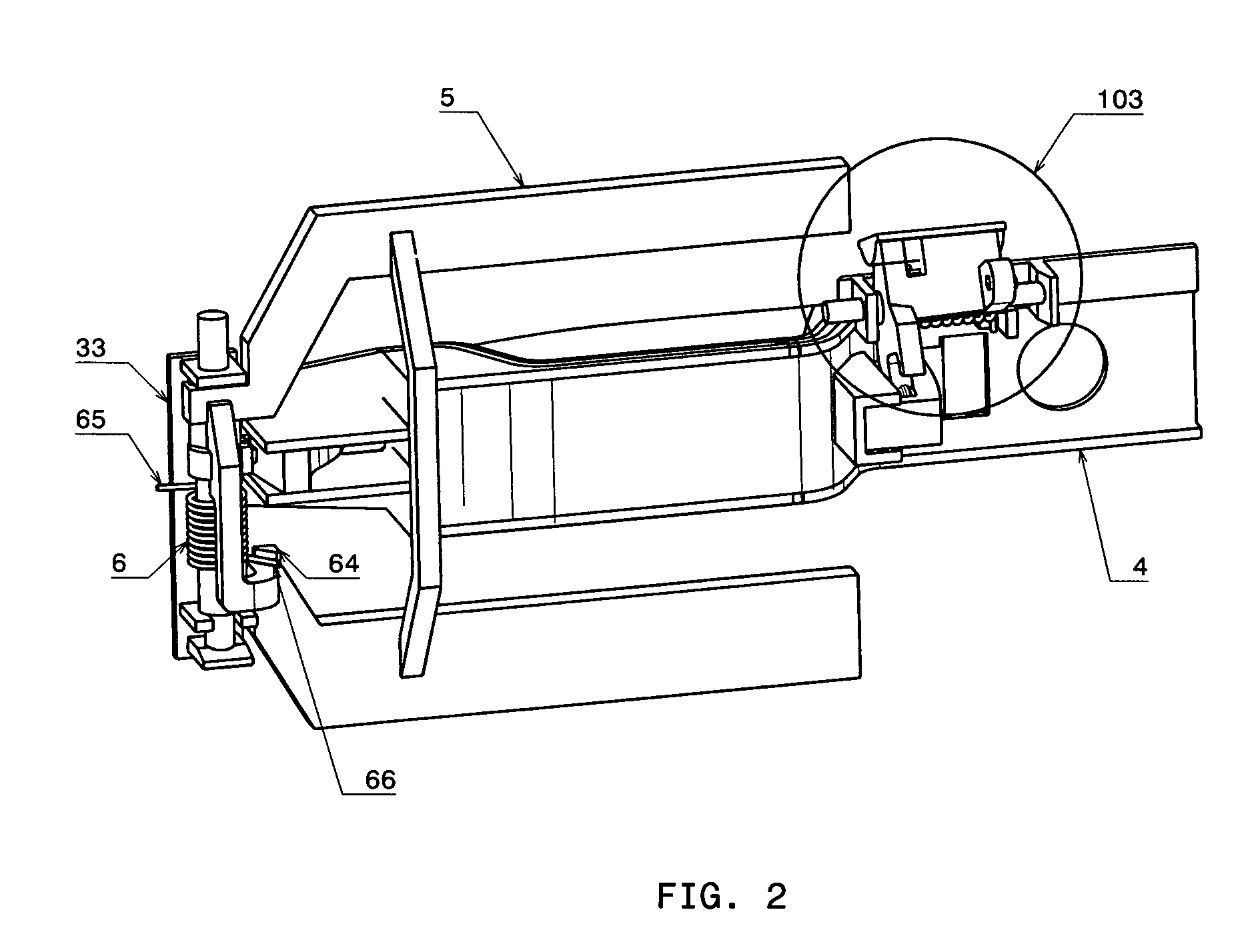
[0037]FIG. 1 and FIG. 2 show a door handle system 101 of a vehicle. It is connected to a latch system (not shown) through a connecting element (not shown), usually a rod or a cable. The door handle system 101, the latch system and the connecting element are installed in vehicle doors. The door handle system 101, the latch system and the connecting element keeps vehicle doors closed, and let vehicle doors open when activated. Activating the door handle assembly 101 by pulling its handle will unlatch the latch system and the vehicle door is unlatched and open.

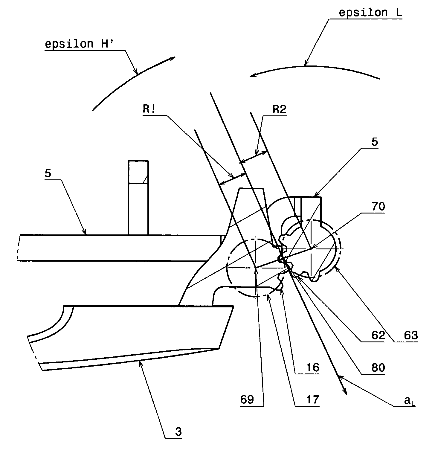
[0038]The door handle assembly 101 also inhibits inadvertent opening of the door 1 when the vehicle is involved in a collision, particularly an impact on a side of the vehicle which results in acceleration and / or forces in a lateral as well as in a vertical direction.

[0039]Referring FIG. 1-4, the door handle assembly 101 comprises a handle 3, a chassis 4, a latch activation mechanism 103, an inertia lever 5 in one embodiment. The...


PUM


Abstract

A directly coupled-inertia activated mechanism that may be incorporated into a door handle assembly and counteracts inadvertent door opening during a side crash. An inertia lever with certain inertia moment in relation ship to that of the handle is coupled to the handle, such that it rotates in the opposite direction of that of the handle when the handle is being pulled. The inertia lever is capable of canceling totally the inertia force causing the handle to move inadvertently to unlatched position during side impact crash, and stops the handle's unlatching move.

Description

CROSS-REFERENCE TO RELATED APPLICATION[0001]This is a continuation of application Ser. No. 12 / 012,329, filed on Feb. 1, 2008, now abandoned.FIELD OF INVENTION[0002]The invention relates generally to the door release system of automotive vehicle, and in particular to a safety device in a door handle assembly as prevention of inadvertent opening of the door during crash, in particular side impact crash.BACKGROUND OF THE INVENTION[0003]Automotive vehicles can be involved in crash accident. In particular side crash can cause the handle to move inadvertently to unlatched position. Doors are unlatched and swung open, thus occupants are exposed to greater risk of being expelled from the vehicles. Many mandatory side crash tests are set up for vehicles. One requirement of these tests is that the vehicle doors remain closed during and after side crash test, in which the vehicle is hit from side. To measure side crash severity, acceleration in terms of G, (1 G=9.8 m / sec^2) is used. Very often...

Claims


Application Information

Patent Timeline
Patent Type & Authority Patents(United States)
IPC IPC(8): E05B3/00
CPCE05B77/06E05B85/16Y10S292/22Y10T292/57
Inventor YANG, LEI
Owner YANG LEI
Why Eureka
Try Eureka