Electrical cable connector latch mechanism

a technology of latch mechanism and electrical connector, which is applied in the direction of coupling parts engagement/disengagement, coupling device connection, electrical apparatus, etc., can solve the problems of undesirable movement of the connector from external loads, electrical problems, etc., and achieve the effect of preventing the disengagement of the latch mechanism, preventing the tilting of the rocker part, and simple push-pull operation

Inactive Publication Date: 2010-11-02
LOROM INDAL
View PDF20 Cites 14 Cited by
  • Summary
  • Abstract
  • Description
  • Claims
  • Application Information

AI Technical Summary

Benefits of technology

[0013]According to a still further aspect of the invention, an electrical coupling includes: a pair of electrical connectors that mate with each other; wherein the coupling may include one or more of the following features: a latch mechanism that works with a simple push-pull operation allowing single-operation engagement by pushing and single-operation disengagement by pulling; a latch mechanism in which tilting of a rocker part is used to disengage the latch; a loop that includes an actuator ramp that is used to tilt a rocker member; a loop that is spring-biased to prevent disengagement of a latch mechanism except when the loop is pulled; a loop that includes a return ramp used to prevent tilting of a rocker part except when the loop is pulled; a molded plastic loop having a pull section, and a head that is within a backshell of one of the connectors; a rocker part in one of the connectors that tilts to press against and resiliently deform part of the other connector, to disengage the latch mechanism; a rocker part that includes a forked end with a pair of fingers, wherein the fingers lift on opposite sides of an anchor when the rocker part is tilted; and a thinned section of a pull loop that allows easy flexing of the loop.

Problems solved by technology

It will be appreciated that movement of the connector from external loads is undesirable.
If the connector is of very fine pitch, small movement can cause electrical problems.

Method used


Image

  • Electrical cable connector latch mechanism
  • Electrical cable connector latch mechanism
  • Electrical cable connector latch mechanism

Examples


Embodiment Construction

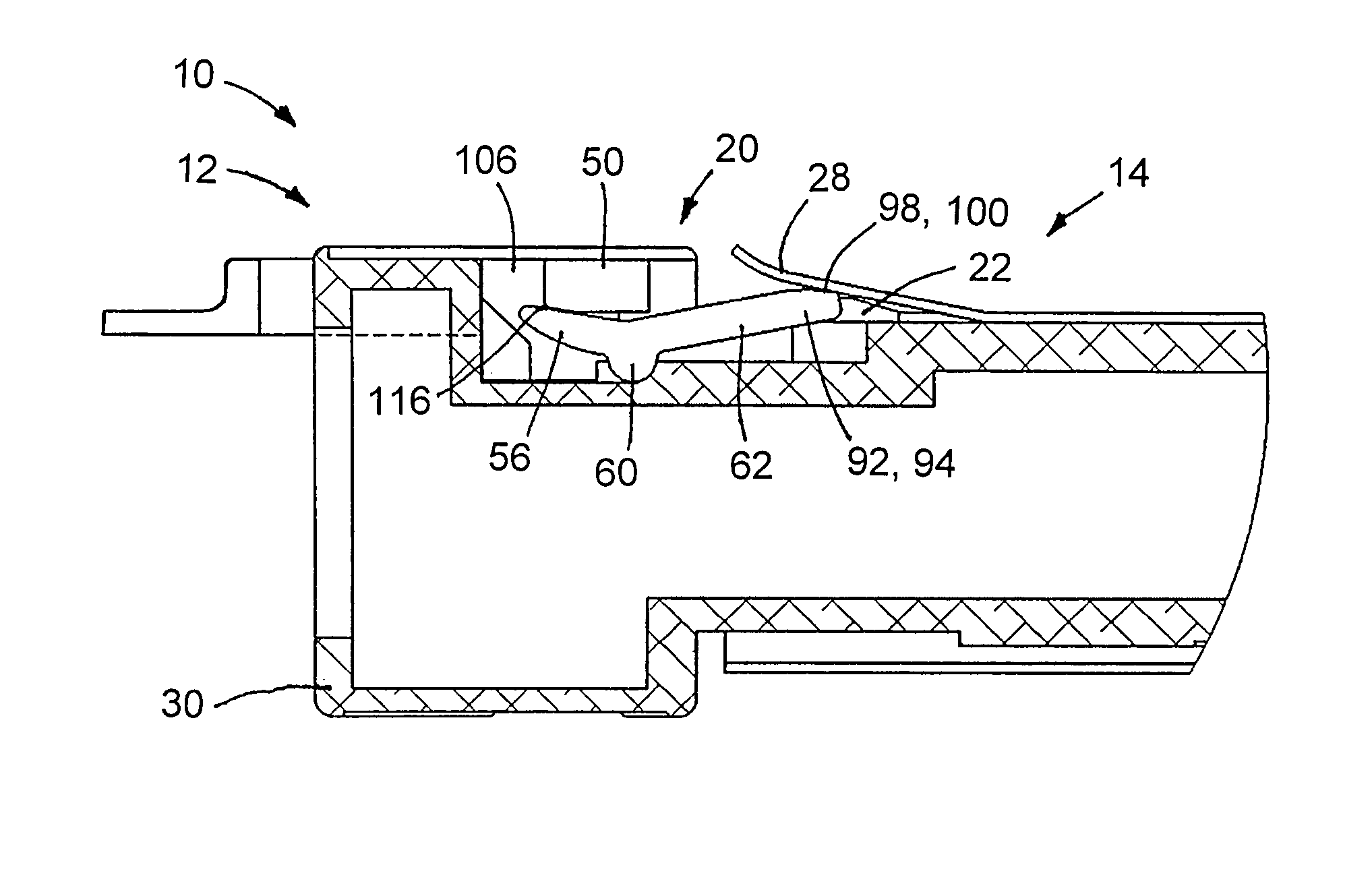
[0035]An electrical cable connector has a latch mechanism wherein the moveable portion is part of the mating receptacle, and the mechanism for unlatching resides in the cable connector. A rocker part is located such that one end extends under the resilient latch member and the other end has a surface which is made to rotate about a pivot point by an externally actuated ramp. The rotation of the rocker lifts the resilient member from its seat and releases the connector latch. The actuating ramp is spring loaded to return to its resting position which is the latched position; it is attached to a loop designed to allow a finger pull action to initiate latch disengagement. Forces and friction resistance is managed such that reliable single-hand operation is achieved, with push to engage and pull to disengage.

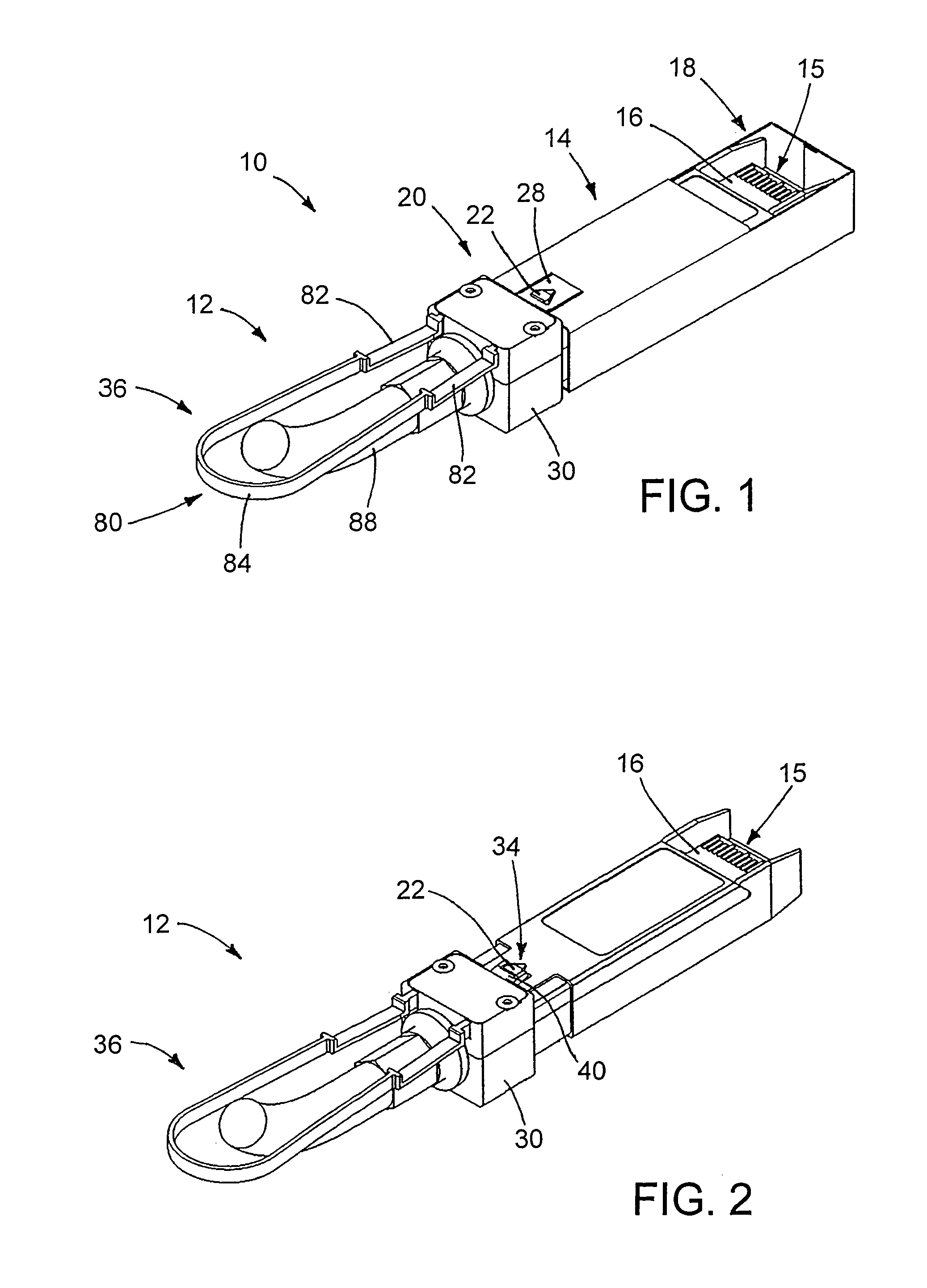
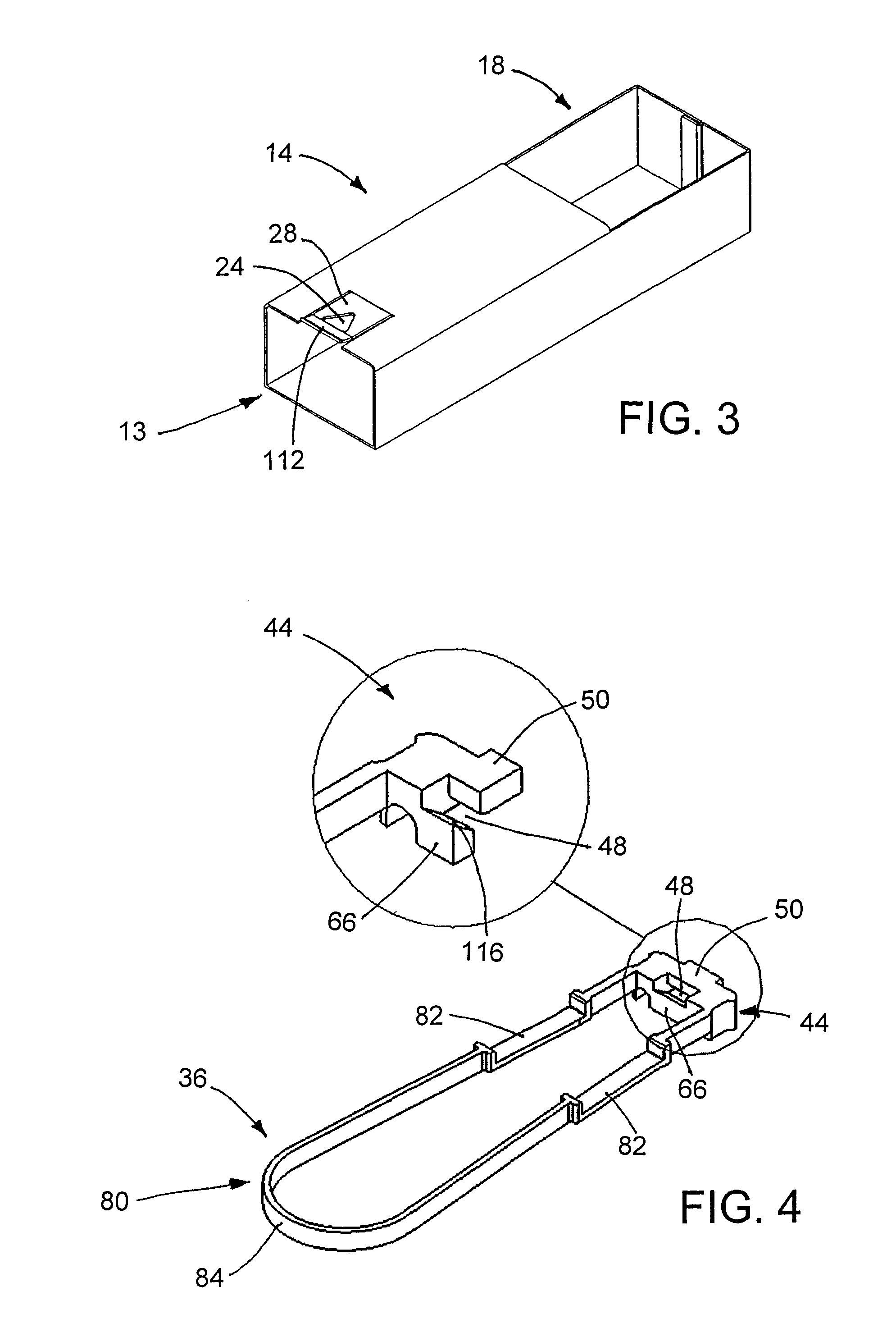
[0036]FIGS. 1-3 shows a mated electrical coupling 10 (FIG. 1) in which a male electrical connector (first connector or cable connector) 12 (FIG. 2) engages a female receptacle (seco...


PUM


Abstract

An electrical cable connector has a latch mechanism wherein the moveable portion is part of the mating receptacle, and the mechanism for unlatching resides in the cable connector. A rocker part is located such that one end extends under the resilient latch member and the other end has a surface which is made to rotate about a pivot point by an externally actuated ramp. The rotation of the rocker lifts the resilient member from its seat and releases the connector latch. The actuating ramp is spring loaded to return to its resting position which is the latched position; it is attached to a loop designed to allow a finger pull action to initiate latch disengagement. Forces and friction resistance is managed such that reliable single-hand operation is achieved, with push to engage and pull to disengage.

Description

[0001]The application claims priority under 35 USC 119 to U.S. Provisional Application No. 61 / 163,135, filed Mar. 25, 2009, which is incorporated herein by reference in its entirety.BACKGROUND OF THE INVENTION[0002]1. Field of the Invention[0003]The invention is in the field of electrical connectors, and more particularly in the field of latches for electrical connectors such as cable connectors.[0004]2. Description of the Related Art[0005]In the field of cable connectors, many types of latches meant to retain the cable in the mating connector have been used. Two basic types are in popular use today: a) a thumbscrew or jackscrew type; and b) a snap latch or lateral spring-loaded latch type.[0006]In the thumbscrew or jackscrew type an actual screw is used to secure the connector or to disengage it. This type has the advantage that once engaged, the attachment is ridged and will easily support hanging cables and other external loads. It will be appreciated that movement of the connect...

Claims


Application Information

Patent Timeline
Patent Type & Authority Patents(United States)
IPC IPC(8): H01R13/62
CPCH01R13/6275
Inventor CROFOOT, LARRY M.VENALECK, JOHN T.
Owner LOROM INDAL
Why Eureka
Try Eureka