Self-ligating orthodontic bracket

a self-ligating, orthodontic technology, applied in the field of self-ligating orthodontic brackets, can solve the problems of affecting the ability of rotation,

Inactive Publication Date: 2011-10-04
LOKAR ROBERT
View PDF38 Cites 67 Cited by
  • Summary
  • Abstract
  • Description
  • Claims
  • Application Information

AI Technical Summary

Benefits of technology

According to one embodiment of the invention, a self-ligating orthodontic bracket apparatus has a body with an archwire slot, a lingual surface for mounting to a tooth and a guide track. The body and guide track form facing surfaces. A clip is engaged between the facing surfaces and is slideably movable in the guide track between an open position such that the archwire slot can receive an archwire and a closed position in which the clip can retain the archwire in the slot. The clip is dimensioned to extend the entire length and height of the slot in the bracket when in the closed position.
In accordance with another aspect of the invention, a self-ligating orthodontic bracket apparatus has a body with an archwire slot and a lingual surface for mounting to a tooth. The body has a guide track. The body has a first beveled surface at one long side of the archwire slot beveled toward the guide track. The body has a second beveled surface at an opposing side of the archwire slot canted in the same general direction as the first beveled surface. A clip is engaged between the guide track and slideably movable between an open position such that the archwire slot can receive an archwire and a closed position in which the clip can retain the archwire in the slot. The clip is installable into the body by passing between the two beveled surfaces in front of the archwire slot to be received into the guide track.

Problems solved by technology

While many different self-ligating orthodontic appliances have been devised and used, they all have drawbacks.
They are either hard to install and adjust or are compromised in their ability to rotate and move teeth to the appropriate position.

Method used


Image

  • Self-ligating orthodontic bracket
  • Self-ligating orthodontic bracket
  • Self-ligating orthodontic bracket

Examples


Embodiment Construction

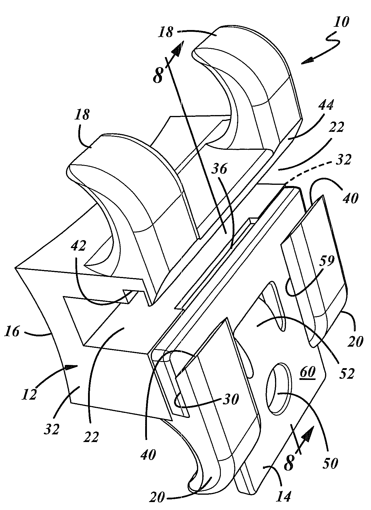
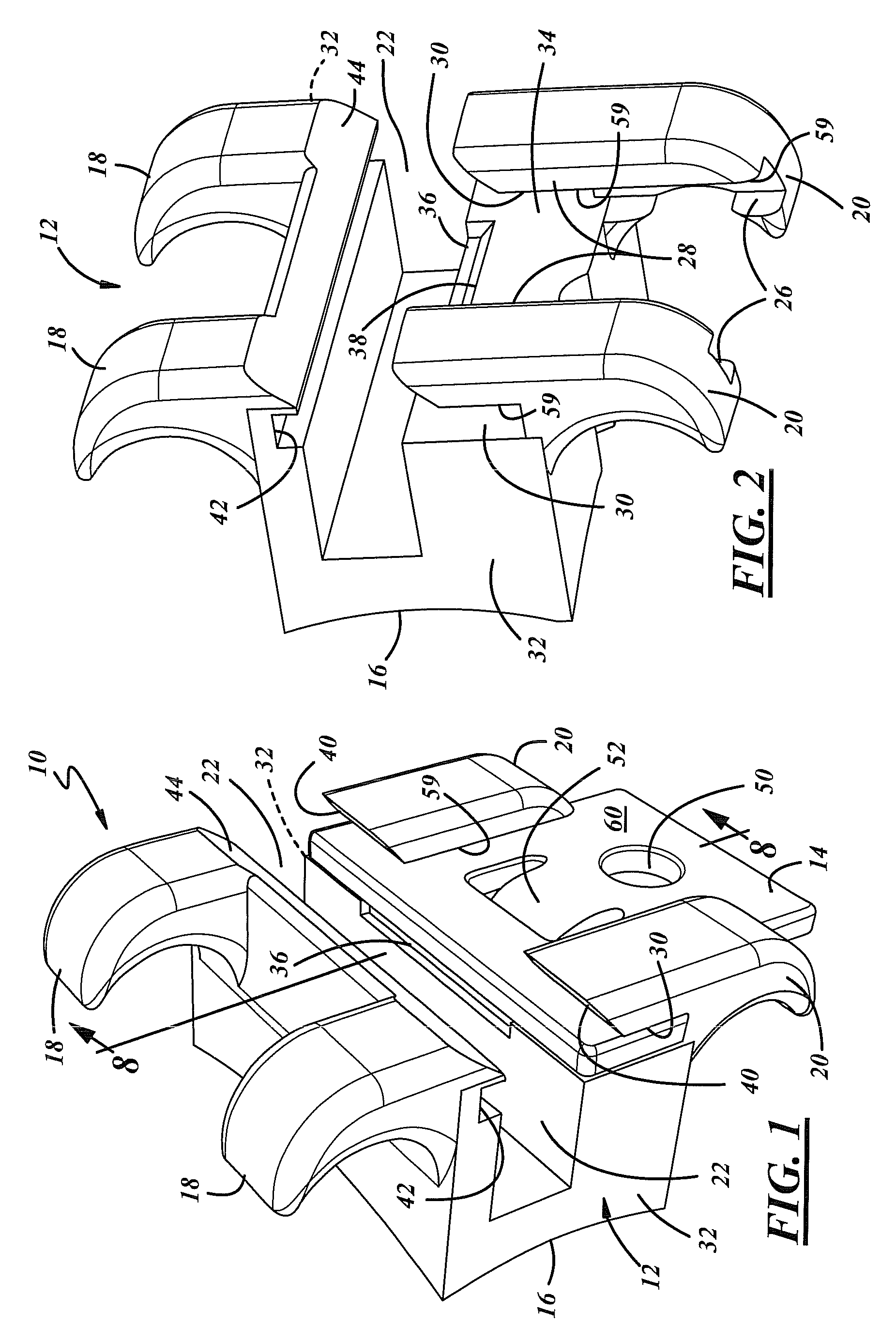
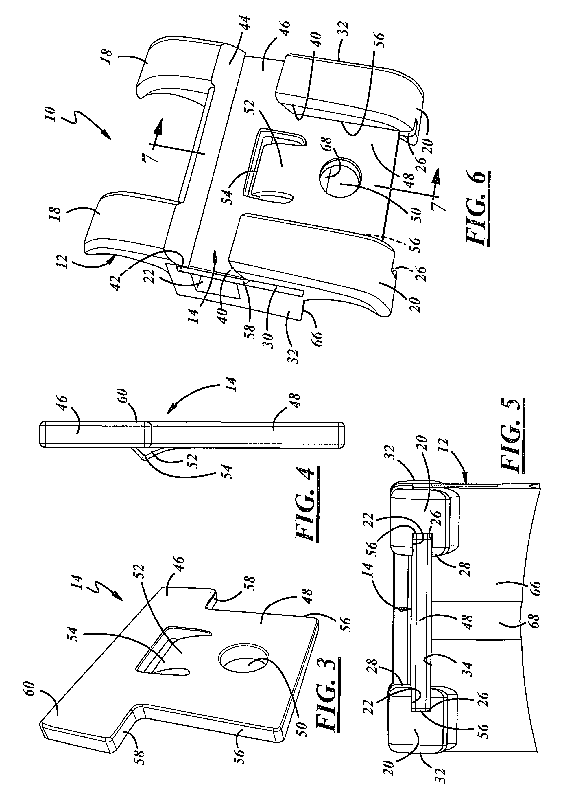
Referring now to FIG. 1, a self-ligating orthodontic bracket 10 has a body 12 and a clip 14. The body 12 as shown in FIG. 2 may be made from a metal material such as titanium. It has a contoured lingual surface 16 for adhering to a tooth member. The figures are oriented to show the bracket 10 as it would be basically viewed on a patient's upper teeth when the patient is sitting upright. When installed on lower teeth, the bracket 10 would be turned upside down from as shown in the drawings. A pair of gingival tie wings 18 and a pair of occlusal tie wings 20 extend from the body 12. An archwire slot 22 extends laterally through the body 12 to hold an archwire 24 as shown in FIG. 7.

As more clearly shown in FIGS. 2 and 5, two slotted internal track sections 26 i.e. track slots 26 run vertically along the axially inner edge 28 of the pair of occlusal tie wings to slideably engage the clip 14. As shown in FIGS. 1, 2 and 6, two laterally outer track sections, cutaway, or pocket sections 30...


PUM


Abstract

According to one embodiment of the invention, a self-ligating orthodontic bracket apparatus has a body with an archwire slot, a lingual surface for mounting to a tooth and a guide track. The body and guide track form facing surfaces. A clip is engaged between the facing surfaces and is slideably movable in the guide track between an open position such that the archwire slot can receive an archwire and a closed position in which the clip can retain the archwire in the slot. The clip is dimensioned to extend the entire length and height of the slot in the bracket when in the closed position.

Description

TECHNICAL FIELDThe field of this invention relates to a self-ligating orthodontic bracket.BACKGROUND OF THE DISCLOSURESelf-ligating orthodontic brackets are in common use for correcting irregularities of tooth position with relation to each other or in relation to the surrounding anatomy. While many different self-ligating orthodontic appliances have been devised and used, they all have drawbacks. They are either hard to install and adjust or are compromised in their ability to rotate and move teeth to the appropriate position.What is needed is a self-ligating orthodontic bracket that is easy to install, and use and has a great capacity for rotating teeth and for performing all the functions necessary to move teeth into their proper position.SUMMARY OF THE DISCLOSUREAccording to one embodiment of the invention, a self-ligating orthodontic bracket apparatus has a body with an archwire slot, a lingual surface for mounting to a tooth and a guide track. The body and guide track form fac...

Claims


Application Information

Patent Timeline
Patent Type & Authority Patents(United States)
IPC IPC(8): A61C3/00
CPCA61C7/287
Inventor LOKAR, ROBERT
Owner LOKAR ROBERT
Why Eureka
Try Eureka