Fluid ejecting apparatus

a technology of ejecting apparatus and nozzle, which is applied in the direction of printing, etc., can solve the problems of ink returning to the nozzle forming face or leaking to the outside when the valve is opened, and achieve the effects of improving the operation efficiency of cleaning operation, reducing decompression space, and good condition

Inactive Publication Date: 2010-02-25
SEIKO EPSON CORP
View PDF1 Cites 24 Cited by
  • Summary
  • Abstract
  • Description
  • Claims
  • Application Information

AI Technical Summary

Benefits of technology

[0009]An advantage of some aspects of the invention is that it provides a fluid ejecting apparatus capable of improving a processing effect and an operating efficiency of a cleaning operation including a suction operation.
[0011]In the invention, the check valve is provided between the cap and the ambient air ventilating unit. The check valve is adapted to cause air to be supplied to the inside of the cap from the outside and to block the reverse flow of air and fluid. As a result, even when the ambient air ventilating unit is provided below the cap, it is possible to prevent the fluid from flowing to the outside when the ambient air ventilating unit is opened. Therefore, it is possible to maintain a good condition that is obtained by a cleaning operation including a suction operation by means of the decompressing unit and to achieve the fluid ejecting apparatus capable of improving the operational efficiency in the cleaning operation.
[0012]In addition, it is preferable to dispose the check valve at a portion in the vicinity of the cap. With this configuration, since the check valve is disposed in the vicinity of the cap, it is possible to reduce a decompressed space between the cap and the check valve, thereby reducing an amount of fluid that reversely flows from the cap to the check valve. As a result, in a case where the ambient air ventilating unit is opened, an amount of fluid that is returned to the cap in conjunction with the supplying of air is reduced, thereby suppressing fluctuation (bubbling) of the fluid in the cap.
[0013]Further, in addition, it is preferable that the check valve functions as an ambient air inflow rate control unit that controls an inflow rate of ambient air flowing in the cap while the ambient air ventilating unit is in an open operation state. With this configuration, since the check valve functions as the ambient air inflow rate control unit that controls the inflow rate of the ambient air flowing in the cap in the open operation state, it is possible to prevent a pressure in the sealed space from being rapidly increased even when the ambient air ventilating unit is opened. For example, in a case where an opening level of the check valve is set to be a predetermined one and an amount of air to be introduced in a unit of time is determined, it is possible to open the ambient air ventilating unit just after the cleaning operation is finished. Namely, only a predetermined amount of air is introduced in the cap per a unit of time so that it is possible to prevent a pressure in the cap from being rapidly increased. As a result, it is possible to suppress fluctuation of the fluid in the cap, thereby eliminating a malfunction due to bubbling of ink.

Problems solved by technology

As a result, a large amount of the ink is returned to the cap together with air when opened to the ambient air, which causes a problem that the ink returned to the cap may adhere to the nozzle forming face or may bubble.
However, ink may possibly leak to the outside when the valve is opened.

Method used


Image

  • Fluid ejecting apparatus
  • Fluid ejecting apparatus
  • Fluid ejecting apparatus

Examples


Embodiment Construction

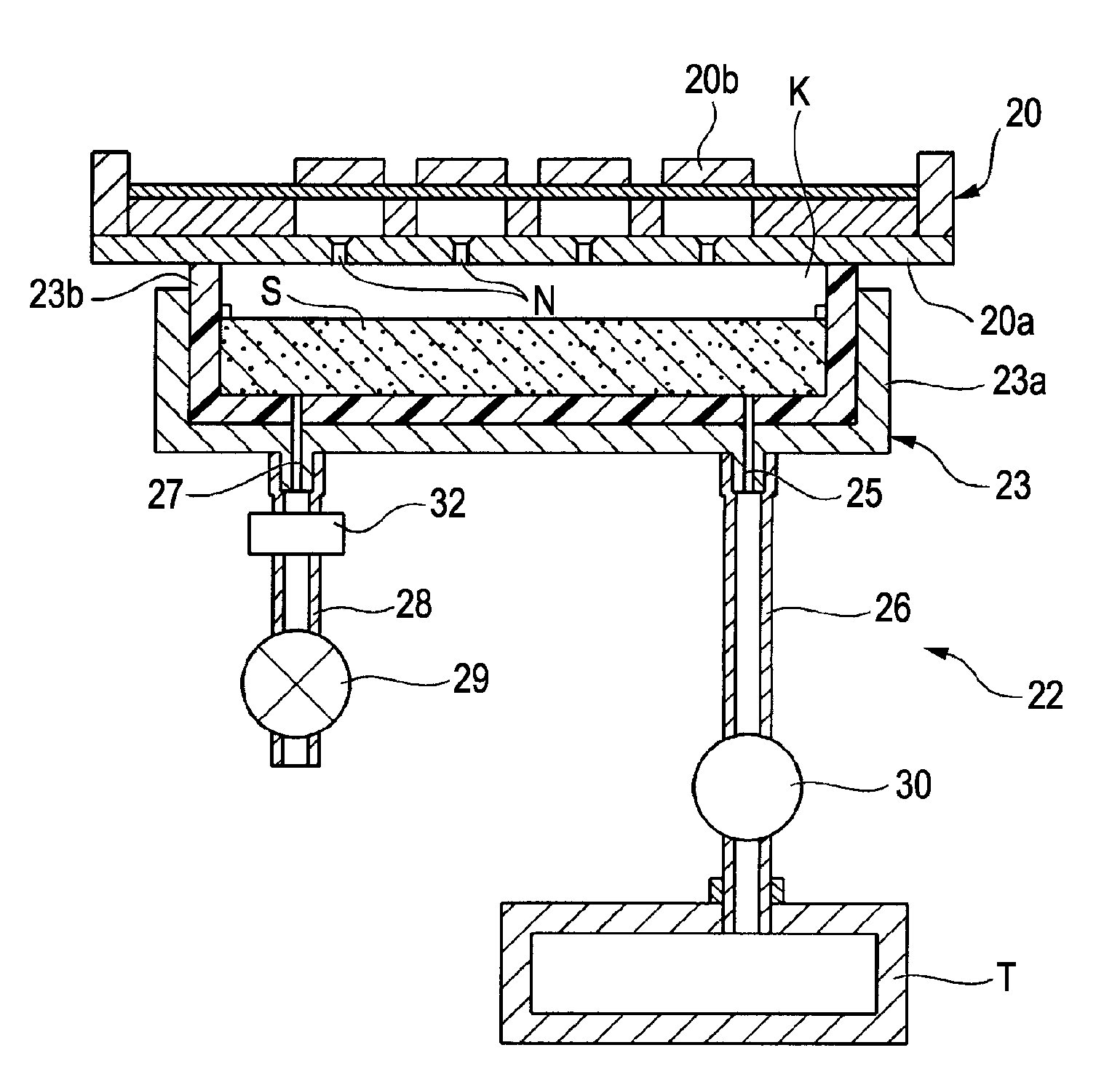
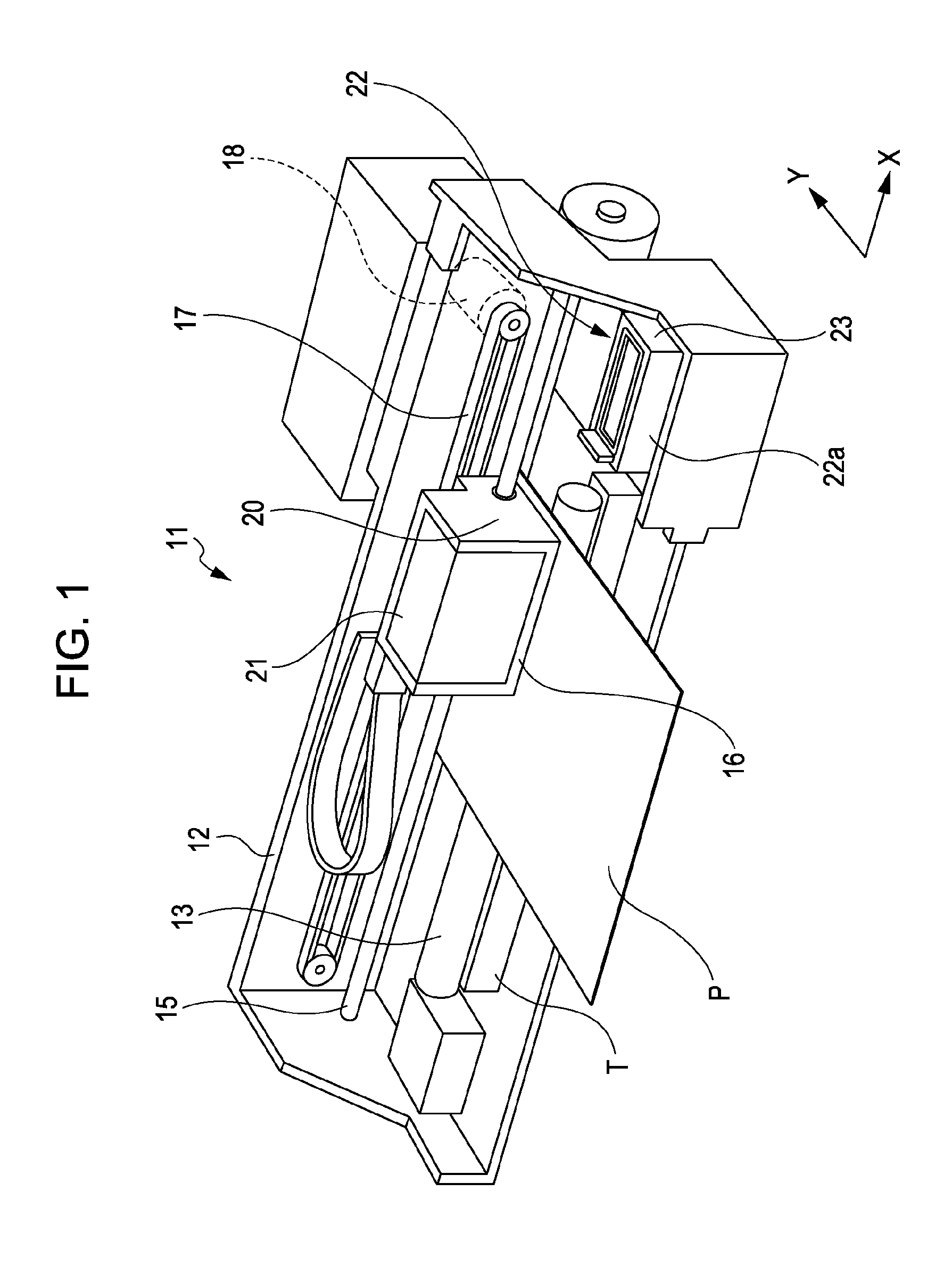
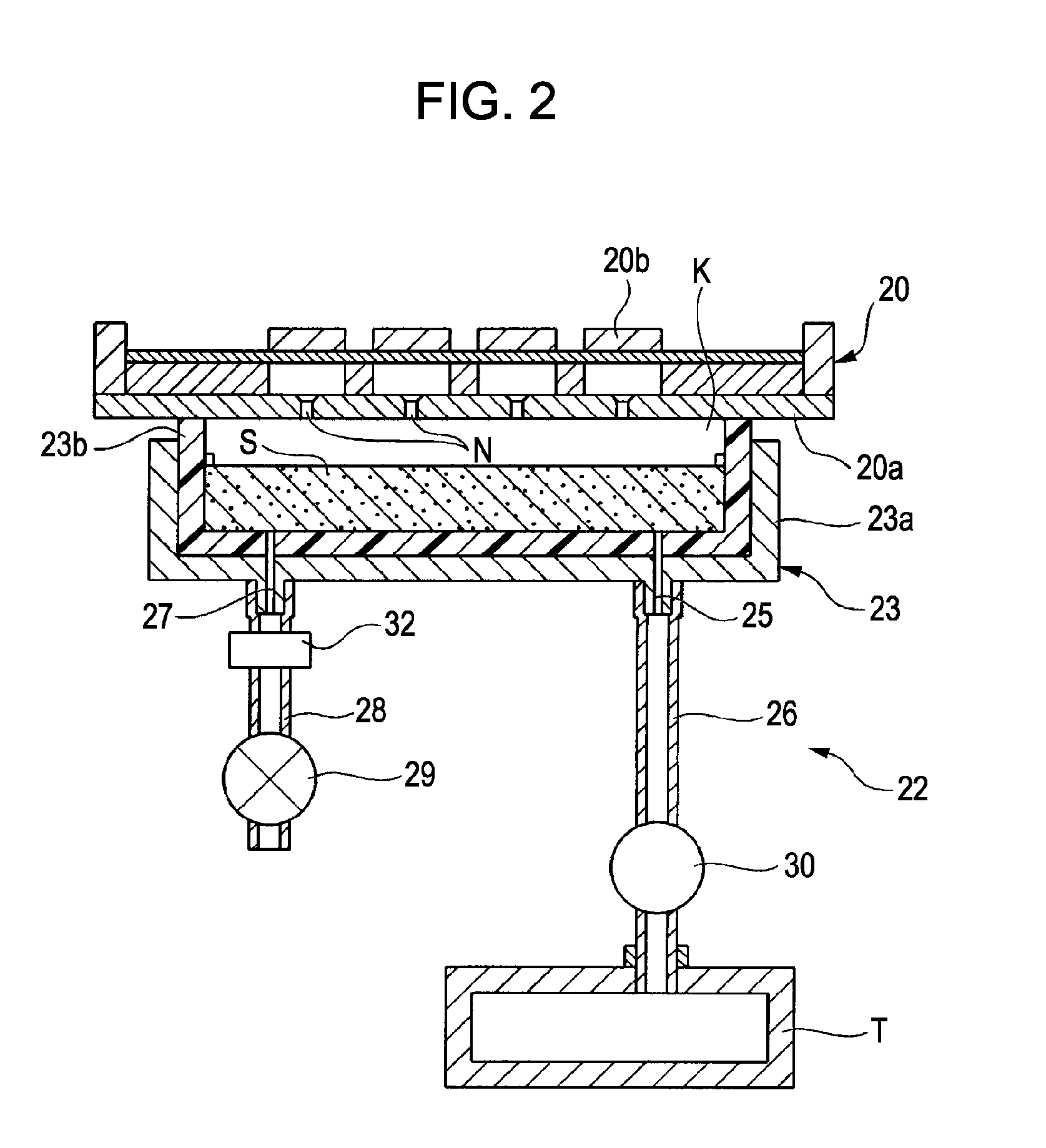
[0017]An embodiment of a fluid ejecting apparatus is described below with reference to FIGS. 1 and 2. FIG. 1 is a schematic perspective view showing a main part of an ink jet printer 11 as the fluid ejecting apparatus. FIG. 2 is a schematic view showing a main part of a maintenance mechanism 22.

[0018]As shown in FIG. 1, the ink jet printer 11 has a frame 12 to which a platen 13 is attached. A recording paper sheet P as a target is fed on the platen 13 by a paper transporting mechanism (not shown). A guide member 15 is attached to the frame 12 in parallel to the longitudinal direction of the platen 13 and a carriage 16 is slidably supported on the guide member 15. The carriage 16 can be reciprocated in a direction (a direction X in FIG. 1) orthogonal to the transporting direction of the recording paper sheet P by a carriage motor 18 via a timing belt 17.

[0019]A recording head 20 is provided on the lower face of the carriage 16. The recording head 20 is equipped with a plurality of no...


PUM


Abstract

A fluid ejecting apparatus includes a fluid ejecting head with a nozzle forming face having formed thereon a plurality of nozzles for ejecting fluid, a cap that is able to form a sealed space together with the nozzle forming face by being in contact with the nozzle forming face, a decompressing unit that is coupled to the cap so as to decompress the sealed space via a first channel, an ambient air ventilating unit that is coupled to the cap so as to open the sealed space to ambient air via a second channel, and a check valve that is provided on the second channel between the cap and the ambient air ventilating unit.

Description

BACKGROUND[0001]1. Technical Field[0002]present invention relates to a fluid ejecting apparatus.[0003]2. Related Art[0004]An ink jet printer, for example, is well known as a fluid ejecting apparatus that ejects a fluid. Such an ink jet printer records characters or images on a recording medium and is configured such that ink (fluid) is selectively ejected from a row of nozzles provided on a recording head (a fluid ejecting head).[0005]In such an ink jet printer, in order to prevent a malfunction in ejection of ink due to clogging in a nozzle, entering of dust, increase in viscosity of the ink or generation of bubbles in the ink, a suction operation is performed such that a nozzle forming face of a recording head is sealed by a cap, a sealed space formed between the cap and the nozzle forming face is decompressed by means of a suction pump, thereby sucking ink having increased viscosity through the nozzle to eject it into the cap. An ambient air ventilating valve is connected to the ...

Claims


Application Information

Patent Timeline
Patent Type & Authority Applications(United States)
IPC IPC(8): B41J2/165
CPCB41J2/16508B41J2/17596B41J2/16523
Inventor MANO, TAKASHI
Owner SEIKO EPSON CORP
Why Eureka
Try Eureka