Flat plate folding type coil spring, pogo pin and manufacturing method

a coil spring and folding type technology, applied in the field of miniaturized coil springs, can solve the problems of reducing the number of turns of the coil spring, unable to provide a sufficient range of motion within a limited range of elasticity, and unable to provide a sufficient range of motion, etc., to achieve satisfactory spring force, high width to height ratio, sufficient range of motion of the prob

Active Publication Date: 2011-10-04
PARK SANG YANG
View PDF11 Cites 36 Cited by
  • Summary
  • Abstract
  • Description
  • Claims
  • Application Information

AI Technical Summary

Benefits of technology

[0024]The exemplary coil spring may be manufactured to be smaller than a conventional one and have a metal strip whose cross section has a high width to height ratio, thereby securing a sufficient range of motion of a probe and a satisfactory spring force.
[0025]Further, the exemplary coil spring may be manufactured to have a wide cross section, thus reducing electrical resistance.
[0026]In addition, the exemplary pogo pin employing the exemplary coil spring may be manufactured by bending a metal strip, thereby reducing manufacturing costs. The miniaturized pogo pin may allow the probe to have a sufficient maximum range of motion.

Problems solved by technology

However, in the case of a conventional pogo pin with a size as small as 0.95 mm or shorter, providing a sufficient range of motion is not possible.
On the other hand, a reduced diameter of a coil spring may result in a decreased spring force or electrical signal loss.
Besides, a decreased number of turns of a coil spring may not provide a sufficient range of motion within a limited range of elasticity of the coil spring.

Method used


Image

  • Flat plate folding type coil spring, pogo pin and manufacturing method
  • Flat plate folding type coil spring, pogo pin and manufacturing method
  • Flat plate folding type coil spring, pogo pin and manufacturing method

Examples


Embodiment Construction

[0041]Exemplary embodiments of the present invention will now be described in detail below with reference to the accompanying drawings, which are incorporated in their entirety by reference herein The following description is provided to assist the reader in gaining a comprehensive understanding of the methods, apparatuses, and / or systems described herein. Accordingly, various changes, modifications, and equivalents of the methods, apparatuses, and / or systems described herein will be obvious to those of ordinary skill in the art. Also, descriptions of well-known functions and constructions may be omitted for clarity and conciseness. Likewise, it should be noted that the drawings are not to precise scale and some of the dimensions are exaggerated for clarity of description in the drawings. In addition, like elements are denoted by like reference numerals throughout the specification and drawings.

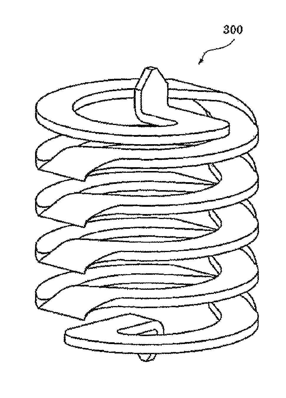
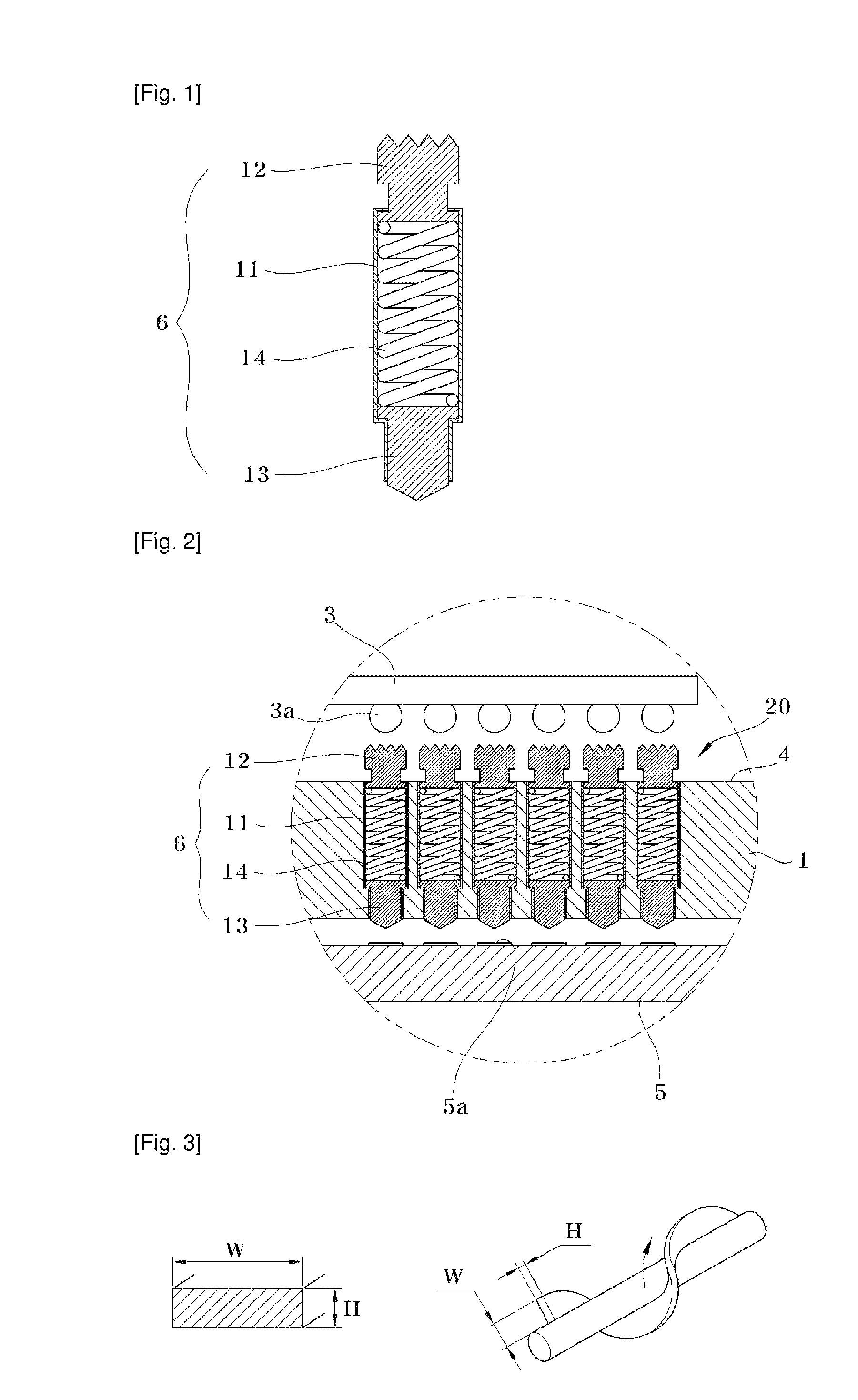
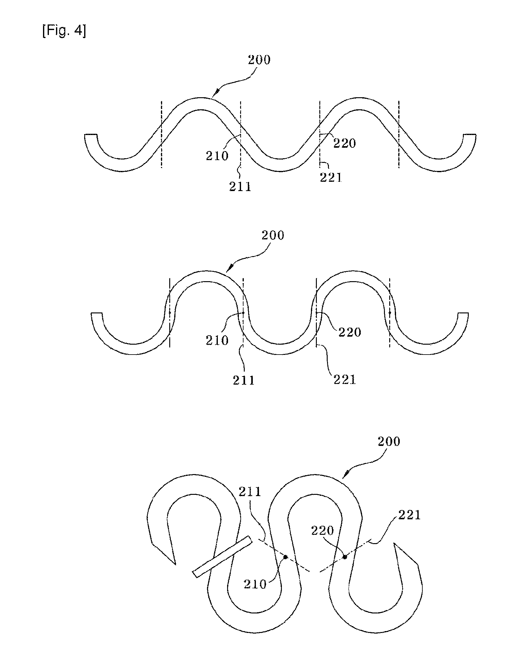
[0042]1. Coil Spring and Manufacturing Method Thereof

[0043]In one embodiment, a coil spri...


PUM

PropertyMeasurementUnit
lengthaaaaaaaaaa
lengthaaaaaaaaaa
sizeaaaaaaaaaa

Abstract

A coil spring, a pogo pin having the coil spring, and manufacturing methods thereof are provided. The method for manufacturing a coil spring includes i) preparing a metal strip 200 with a periodically repeated U- or S-shape pattern, and ii) bending the metal strip 200 at one or more inward bending points 210 and at one or more outward bending point 220, which are formed on the metal strip 200, in opposite directions, the inward bending point and the outward bending point being spaced apart from each other. The coil spring and the pogo pin may be manufactured to be small in size and low in manufacturing costs as compared with conventional ones. Further, the coil spring and the pogo pin may provide a sufficient maximum range of motion and spring force of a probe.

Description

CROSS REFERENCE TO RELATED APPLICATION[0001]This application claims the priority of Korean Patent Application No. 10-2008-0077238, filed on Aug. 7, 2008, Korean Patent Application No. 10-2008-0079910, filed on Aug. 14, 2008, and Korean Patent Application No. 10-2009-0054228, filed on Jun. 18, 2009, in the KIPO (Korean Intellectual Property Office), the disclosure of which are incorporated herein in their entirety by reference. Further, this application is the National Phase application of International Application No. PCT / KR2009 / 003815, filed Jul. 13, 2009, which designates the United States and was published in Korean. Each of these applications is hereby incorporated by reference in their entirety into the present application.TECHNICAL FIELD[0002]The following description relates to a miniaturized coil spring which is formed by bending a metal strip in a periodically repeated pattern, a pogo pin employing the coil spring, and methods for manufacturing the coil spring and the pogo ...

Claims


Application Information

Patent Timeline
Patent Type & Authority Patents(United States)
IPC IPC(8): H01R12/00
CPCB21F3/02G01R1/06722F16F1/042Y10T29/49609
Inventor PARK, SANG YANG
Owner PARK SANG YANG
Why Eureka
Try Eureka