Probe holder providing constant lift-off for in-line bar-pipe testing

a technology of in-line bar-pipe testing and probe holder, which is applied in the direction of analysing solids using sonic/ultrasonic/infrasonic waves, measuring devices, instruments, etc., can solve the problems of rapid and continuous relative movement between the probes, exacerbated problems, and maintain constant lift-off, so as to reduce the pressure between the spacer and the inspected surface, avoid excessive wear of the spacer, and increase the surface area of the spacer

Active Publication Date: 2017-08-29
OLYMPUS SCI SOLUTIONS AMERICAS
View PDF5 Cites 1 Cited by
  • Summary
  • Abstract
  • Description
  • Claims
  • Application Information

AI Technical Summary

Benefits of technology

[0010]The purpose of the invention is to alleviate problems with prior art solutions. The invention is a probe holder assembly which comprises a frame, with two attached rollers and with mechanical links attaching a probe to the frame. The weight of the probe holder assembly rests on the rollers which are in contact with the surface of the bar to be inspected, and rotate in counter-rotation to the rotation of the bar. The mechanical links allow motion of the probe only in the radial direction of the bar, the radial direction being stably defined as perpendicular to the plane through the axes of the rollers in contact with the surface of the bar. The base of the probe, in close proximity to the eddy current coils, comprises a spacer which defines the lift-off distance. The spacer is made of soft material in order to avoid damaging the inspected surface, but since most of the weight of the probe holder assembly rests on the rollers, there is very little pressure between the spacer and the inspected surface, thereby avoiding excessive wear of the spacer. The spacer is long in the axial direction of the bar, which increases the surface area of the spacer, thereby further reducing the pressure between the spacer and the inspected surface. The rollers are also long in the axial direction thereby enabling the probe to be used in good alignment to the very end of a bar. The allowable range of motion of the probe in the radial direction is sufficient to allow inspection of bars with a wide range of diameters, without needing to make any adjustment to the probe holder assembly. The motion of the probe also serves to ensure that if the roller diameters change due to wear, the probe lift-off will not change.
[0011]It is a purpose of the present invention to maintain a constant lift-off distance utilizing a spacer made of soft material to avoid damaging the inspected surface.
[0012]It is a further purpose of the present invention to have the weight of the probe holder assembly resting on two rollers, with only the much lesser weight of the probe resting on the spacer, whereby the reduced pressure between the spacer and inspected surface reduces the wear on the spacer.
[0013]It is a further purpose of the present invention to have a spacer which is long in the axial direction, whereby the area of the spacer is increased, and the pressure between the spacer and inspected surface and the wear on the spacer are both further reduced.
[0015]It is a further purpose of the present invention to have a probe holder which requires no adjustment or replacement when inspecting bars of different diameter.

Problems solved by technology

A significant difficulty in the prior art is maintaining constant lift-off under conditions of in-line testing, in which there is rapid and continuous relative movement between the probe and the inspected surface.
The problem is exacerbated by the fact that the bar being tested is often not perfectly round and / or the rotation of the bar is eccentric.
There are multiple problems with this prior art approach.
If the spacer is made of hard material, then the pressure is liable to damage the inspected surface by causing scratches.
On the other hand, if the spacer is made of soft material, then the high speed relative motion between the soft material and the alloy surface will result in rapid wear of the soft spacer.
As the spacer wears down, the lift-off will change, resulting in detection errors until the spacer can be replaced during a maintenance procedure which will disrupt production.
Another problem with the prior art solutions is that the motion of the probe as the bar rotates needs to be accurately aligned with the radial direction of the bar.
Any rotation of the probe, or translation parallel to the surface of the bar, will lead to defect detection errors.
Yet another problem with prior art solutions is that the probe holder is customized for a particular bar diameter.
This means that the probe holder must be replaced and / or re-adjusted every time the bar size is changed, which is often a labor intensive operation resulting in costly disruption to production.
Yet another problem with prior art solutions is that the probe holder often does not allow the probe to be used in good alignment to the very end of a bar.

Method used


Image

  • Probe holder providing constant lift-off for in-line bar-pipe testing
  • Probe holder providing constant lift-off for in-line bar-pipe testing
  • Probe holder providing constant lift-off for in-line bar-pipe testing

Examples


Embodiment Construction

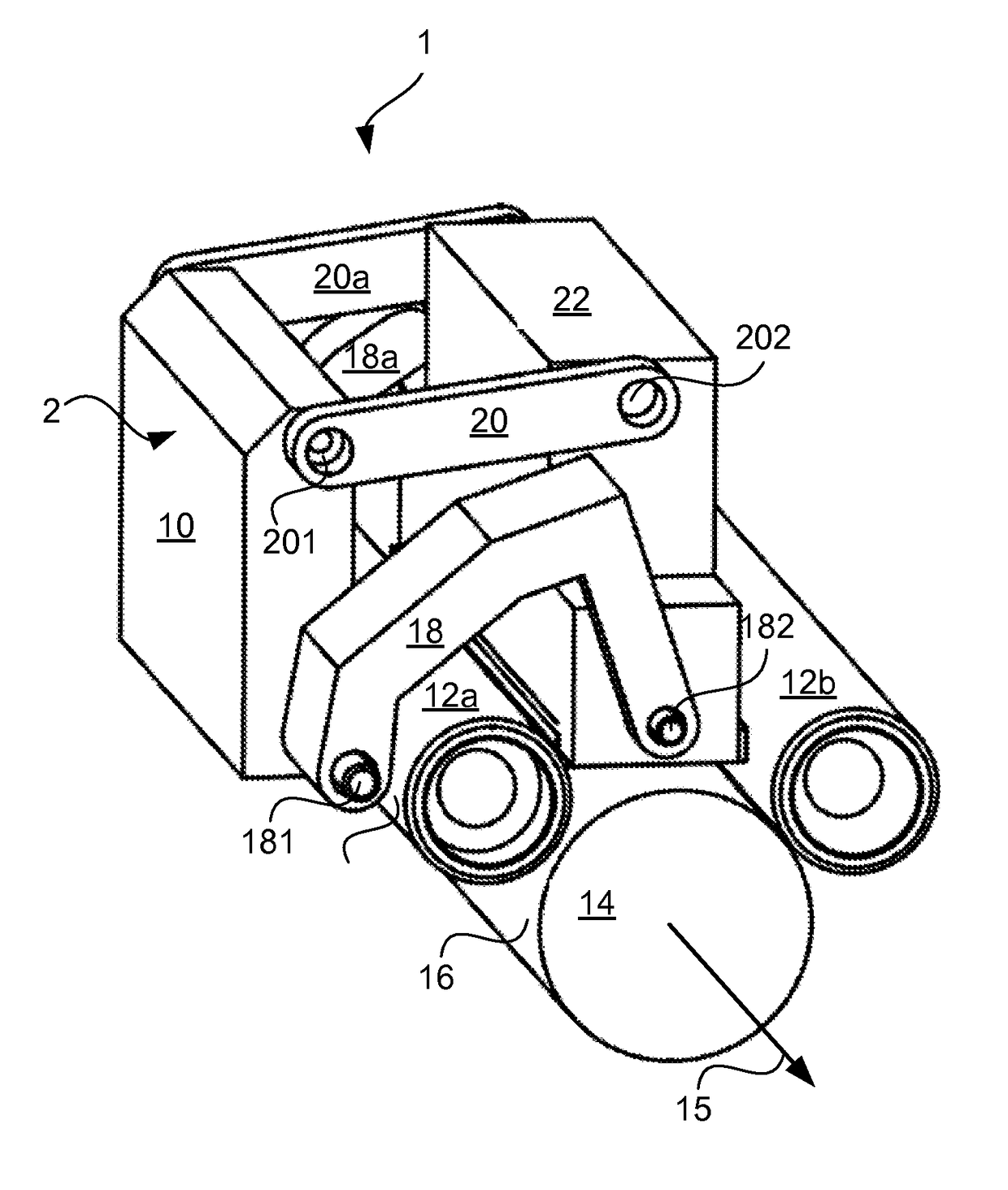
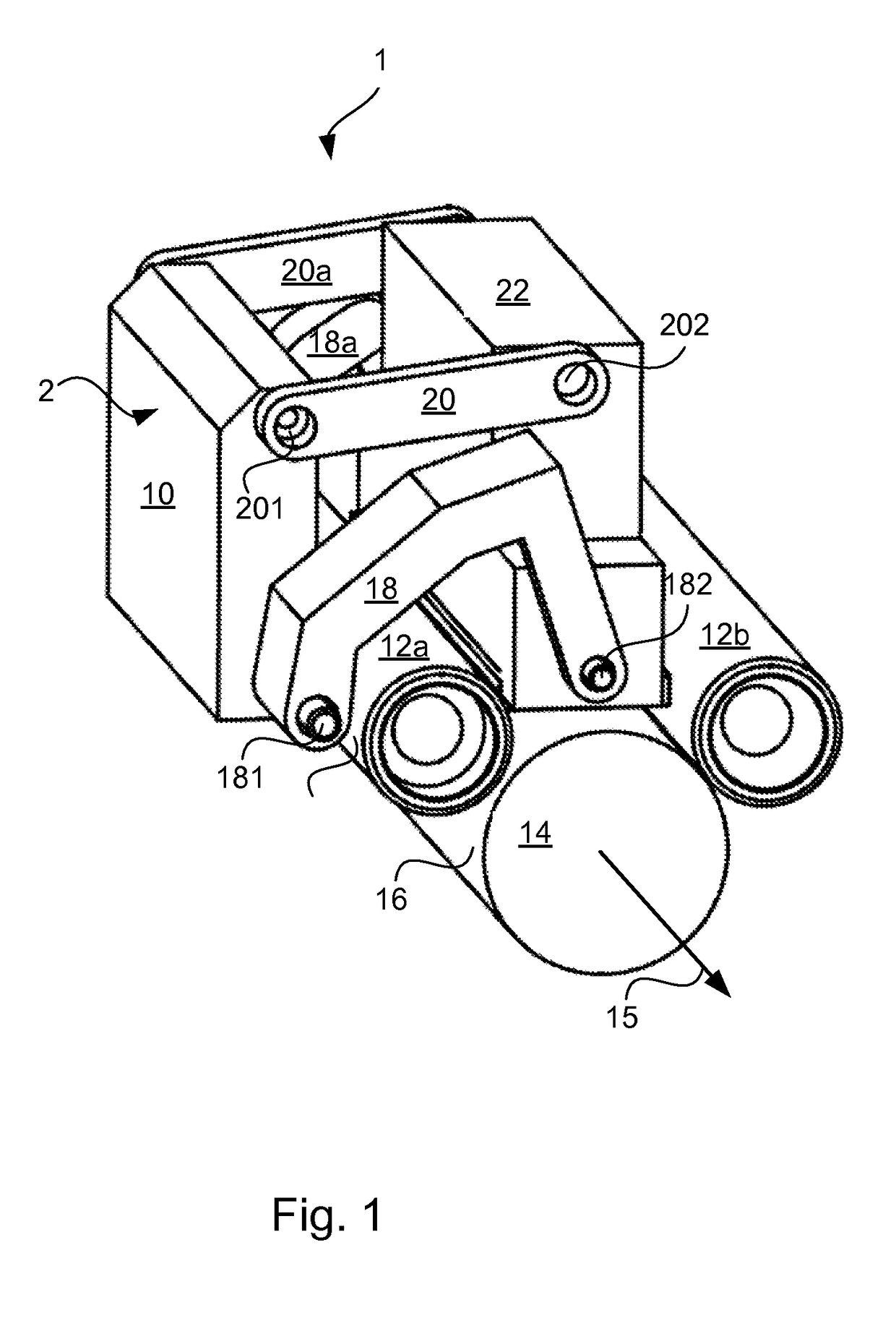
[0023]FIG. 1 shows a probe assembly 1 according to the present disclosure. Probe assembly 1 includes a probe 22 and a probe holder assembly 2. Probe holder assembly 2 comprises a frame 10, rollers 12a and 12b, and mechanical links 18, 18a, 20 and 20a. Mechanical links 18 and 18a are attached at one end to the frame 10 by means of freely rotatable pivot joints 181 and 181a (not shown), and at the other end to probe 22 by means of freely rotatable pivot joints 182 and 182a (not shown). Mechanical links 20 and 20a are attached at one end to the frame 10 by means of freely rotatable pivot joints 201 and 201a (not shown), and at the other end to the probe 22 by means of freely rotatable pivot joints 202 and 202a (not shown). Rollers 12a and 12b are generally cylindrical, and are attached to frame 10 such that they are free to rotate about their respective axes, but the axes are in fixed geometrical relation to frame 10. The outer surfaces of rollers 12a and 12b are in contact with outer ...


PUM

PropertyMeasurementUnit
areaaaaaaaaaaa
weightaaaaaaaaaa
lift-off distanceaaaaaaaaaa

Abstract

Disclosed is a probe holder for in-line inspection of the surface of bars of high value alloys. To attain full coverage of the inspected surface, the bar is rotated while either the bar or the probe holder is translated. The probe holder of the invention ensures constant probe lift-off by allowing the probe to move freely under its own weight, while constraining the motion to be only in the radial direction of the bar. The lift-off distance is defined by a spacer which is made of soft material to avoid damaging the inspected surface. Although the spacer is soft, its wear due to friction with the rotating bar is minimized by minimizing the pressure between the spacer and the bar. This is achieved by resting most of the mechanism weight on two rollers, with only the much smaller weight of the probe resting on the spacer.

Description

FIELD OF THE INVENTION[0001]The invention relates to use of probes, such as eddy current or ultrasonic probes, for in-line non-destructive testing / inspection (NDT / NDI) of surface or near-surface flaws in bars of high value alloys.BACKGROUND OF THE INVENTION[0002]The term “in-line” refers to continuous NDT / NDI which occurs within the production line in which an alloy is produced or finished. Testing occurs continuously as the final product emerges from the production line, and its purpose is to ensure that the surface of the high value alloy is smooth, with no flaws, cracks or scratches. The bars to be inspected are generally cylindrical, the length of the axis of the cylinder usually being much larger than its diameter. Hereafter, a direction parallel to the axis of the bar will be referred to as an “axial” direction, and a direction perpendicular to the axis of the bar will be referred to as a “radial” direction. The bar cylinders may be comprised of solid material throughout, or t...

Claims


Application Information

Patent Timeline
Patent Type & Authority Patents(United States)
IPC IPC(8): G01N29/04G01N29/265G01N29/26G01N29/22G01N29/06G01N27/90G01N27/82
CPCG01N29/225G01N27/9093G01N29/041G01N29/06G01N29/262G01N29/265G01N27/82G01N2291/0289G01N2291/2634G01N27/902G01N29/24G01N2291/0234
Inventor FAUCHER, DENIS
Owner OLYMPUS SCI SOLUTIONS AMERICAS
Why Eureka
Try Eureka