Locking shoulder joint

a shoulder joint and locking technology, applied in the field of prosthetic shoulder joints, can solve the problems of increasing comfort during walking, requiring excessive repositioning by users, and unable to use these joints in the free, and achieve the effect of adequate range of motion

Active Publication Date: 2008-10-21
COLLEGE PARK IND INC
View PDF2 Cites 12 Cited by
  • Summary
  • Abstract
  • Description
  • Claims
  • Application Information

AI Technical Summary

Benefits of technology

[0006]It is therefore a primary object of this invention to provide a small, lightweight prosthetic shoulder joint with an adequate range of motion around both axes.
[0007]It is a further object of the invention to provide a prosthetic joint with easily adjustable friction about the abduction-adduction axis.
[0008]It is a further object of the invention to provide a prosthetic joint with the capability to readily alter the flexion-extension axis between two states-fully locked and free-to-swing.

Problems solved by technology

When the friction is high, the user requires excessive force to reposition.
When it is too low, inadvertent slippage may cause a problem.
Furthermore it is impossible to use these joints in the free-swing mode that greatly increases comfort during walking.
Although there are some prosthetic knee joints that provide the user with a free-swing mode in the knee joint, such as those described in U.S. Pat. No. 6,764,520 issued on Jul. 20, 2004 to Deffenbaugh et al., U.S. Pat. No. 4,614,518 issued on Sep. 30, 1986 to Lehneis et al. and U.S. Pat. No. 4,520,512 issued on Jun. 4, 1985 to Lehneis et al., these free-swing knee joints are not suitable for a shoulder joint.
The free-swing modes in these prosthetic knee joints are not feasible for use in a shoulder joint because the free-swing mode is either on or off and when on, it is completely free to swing without any intermediary locking positions.
Prior prosthetic shoulder joints also do not provide a means for efficiently managing control cables necessary to activate and control the movements of the prosthesis.
Such cables just hang loose and get caught up in or tangled around the prosthesis during movement of the joint.

Method used


Image

  • Locking shoulder joint
  • Locking shoulder joint
  • Locking shoulder joint

Examples


Embodiment Construction

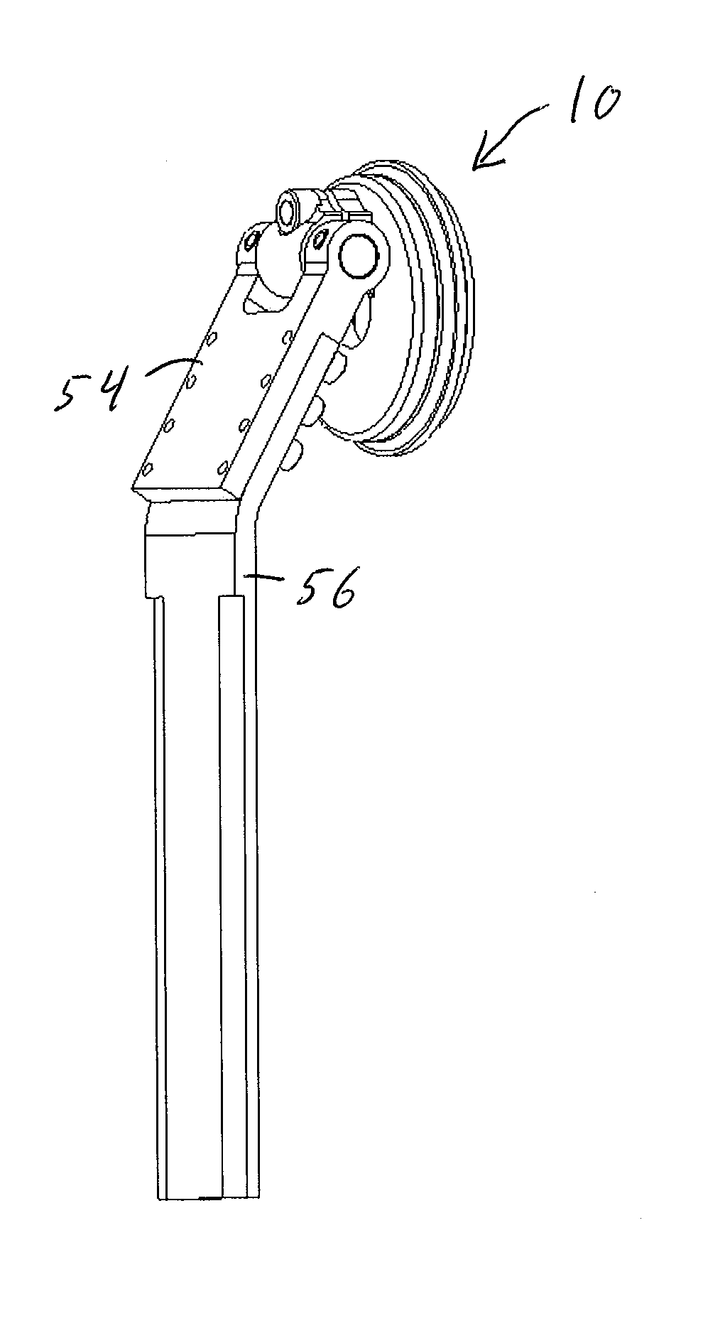
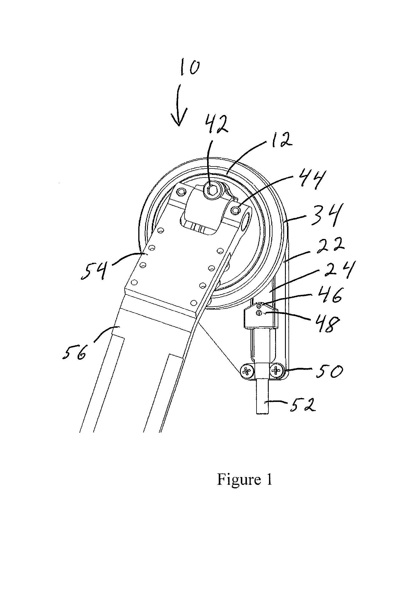
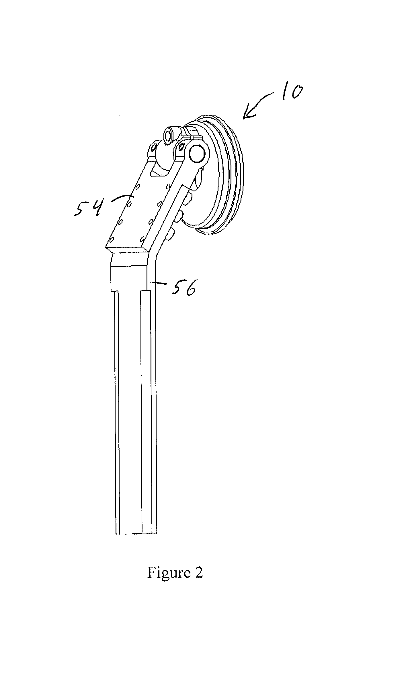
[0040]The invention features a prosthetic shoulder joint that preferably locks in 36 positions, or every 10 degrees. This resolution is preferred to allow the user to position the limb as needed. The user can trip the lock mechanism even when the locking plungers are not lined up, and as soon as the joint reaches the nearest 10° position, the lock auto-engages. There is no need to pre-align the locking components manually, thus making it easier to engage the lock. Additionally, the joint can be unlocked under a moderate load, a feature seldom found in locking prosthetic joints.

[0041]The lock may easily be engaged or disengaged with a manual lever actuator. Alternatively, the lock may be actuated using a remote mechanical or an electric actuator. Remote actuation is needed when the user cannot access the lock release mechanism directly. For example, a bilateral amputee would benefit from the optional electric actuator.

[0042]An alternator mechanism activates the lock. Thus, only pull ...


PUM


Abstract

A locking shoulder joint adapted to be attached to a user's shoulder, generally comprising a rotor provided with a plurality of radially positioned pins, that rotates relative to a stator, and a cam provided with one or more plungers adapted to engage said rotor pins to releasably lock said rotor in position selected by said user, all of which act to move a humeral member in a direction corresponding to a flexion / extension direction of the shoulder joint; and a yoke coupled to an axle for moving the humeral member in a direction corresponding to an abduction / adduction direction of the shoulder joint.

Description

CROSS-REFERENCE[0001]This is a continuation in part of U.S. Provisional Patent Application Ser. No. 60 / 647,844 filed on Jan. 26, 2005.FIELD OF THE INVENTION[0002]This invention relates to prosthetics and more specifically to a prosthetic shoulder joint.BACKGROUND OF THE INVENTION[0003]A number of prosthetic shoulder joints have been developed to facilitate shoulder movement in a prosthetic system. These generally consist of two friction joints in close proximity to replace the anatomical motions of flexion-extension and abduction-adduction. The user must overcome this friction to position the joint. When the friction is high, the user requires excessive force to reposition. When it is too low, inadvertent slippage may cause a problem. Furthermore it is impossible to use these joints in the free-swing mode that greatly increases comfort during walking.[0004]Although there are some prosthetic knee joints that provide the user with a free-swing mode in the knee joint, such as those des...

Claims


Application Information

Patent Timeline
Patent Type & Authority Patents(United States)
IPC IPC(8): A61F2/66
CPCA61F2/581A61F2/68A61F2/72A61F2002/5041A61F2002/5043A61F2002/5093A61F2002/6818A61F2002/6854A61F2002/701A61F2002/707A61F2/70
Inventor WILLIAMS, III, T. WALLEYHANSON, WILLIAM J.
Owner COLLEGE PARK IND INC
Why Eureka
Try Eureka