Gantry robotics system and related material transport for contour crafting

a robotic system and contour technology, applied in the direction of manufacturing tools, hoisting equipment, bridges, etc., can solve the problems of difficult and difficult construction, difficulty in efficient use of time of many individuals, and difficulty in reducing the effect of compressive strength

Active Publication Date: 2011-10-04
UNIV OF SOUTHERN CALIFORNIA
View PDF54 Cites 39 Cited by
  • Summary
  • Abstract
  • Description
  • Claims
  • Application Information

AI Technical Summary

Problems solved by technology

Despite all of the centuries of development, however, there can be difficulties and problems.
Construction is usually very labor intensive.
This can be very costly.
Simultaneously using the time of numerous individuals in an efficient manner can also be challenging.
The results of the construction effort can also be inconsistent.
This can be caused by differences in the skills, efforts, supervision and techniques employed by those that work on the structures.
Construction may also result in wasted material.
For example, when wood is used, standard, off-the-shelf lengths must often be cut to meet design requirements, resulting in waste.
Construction using manual labor can also be very time-consuming, requiring months and, in some instances, years to complete.
Construction can also be hazardous.
Many construction workers are killed or seriously injured at construction sites, including about 500,000 in the United States alone.
Design of light weight large gantries has been seen as a challenge for applications that require accuracy.
Moreover, large size results in flexing of structural members the increase in stiffness of which usually results in added weight, given a material (aluminum, steel, composites, etc.) for the members.
Also, material delivery to the nozzle of such gantry systems, which move in a large volume in the 3D space, have proven to be difficult to implement.
Furthermore, delivery of the material to the nozzle given the localized motions of the nozzle (rotation and deflections) can also present significant challenges.

Method used


Image

  • Gantry robotics system and related material transport for contour crafting
  • Gantry robotics system and related material transport for contour crafting
  • Gantry robotics system and related material transport for contour crafting

Examples


embodiment 500

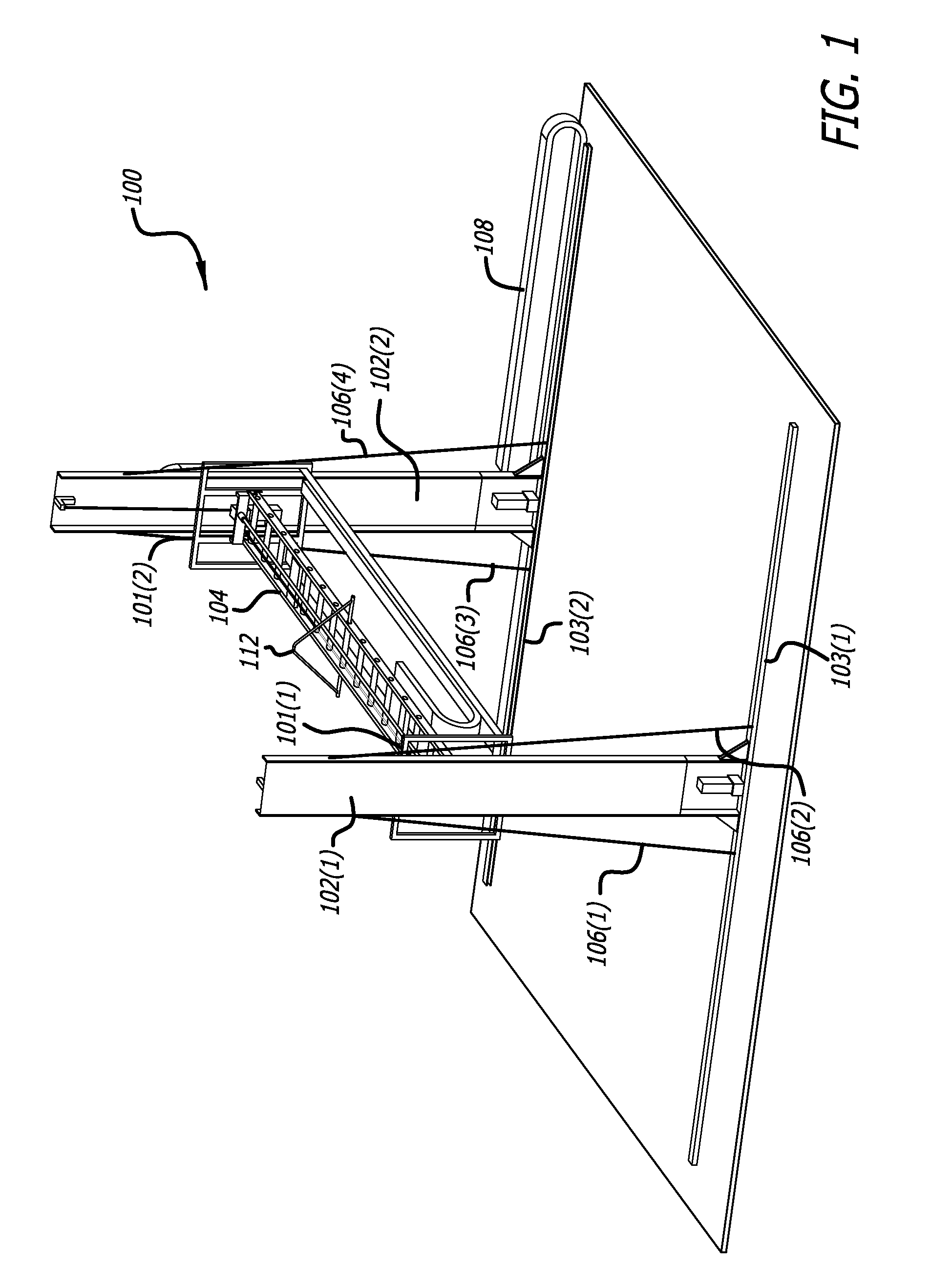
[0047]FIG. 5B shows an alternate embodiment 500 for connecting the bridge to the columns. As can be appreciated, one difficulty with making gantry system of FIG. 1 deployable for use on construction sites is the alignment problem. If the distance between the rails is not equal to the length of the Y bridge then the misalignment could impede and jam the up and down movement of the Y bridge. To allow for errors in misalignment of the rails, one end of the Y bridge 520 may be connected by means of a hinge 524 to its corresponding vertical slide mechanism 522, as shown in FIG. 5B. Given that the other end of the Y bridge is connected to the corresponding column by bearing mechanisms at least in two points with some vertical distance; and given that both ends of the Y bridge are suspended by cables (not shown), or are engaged with the columns through rack and pinions, the entire structure will still have no degree of freedom and will hence rigidly stand unless moved by motors. Under this...

embodiment 1300

[0066]FIGS. 13A-13C depict an alternative embodiment 1300 for routing the material hose 107 (not shown) through cable tracks is an independent routing approach by means of a passive articulated arm. The advantage of this method / embodiment is reduction in the hose length and the possibility of using larger diameter hoses, which would be problematic to route through cable carriers (because of large diameter and large radius of bend).

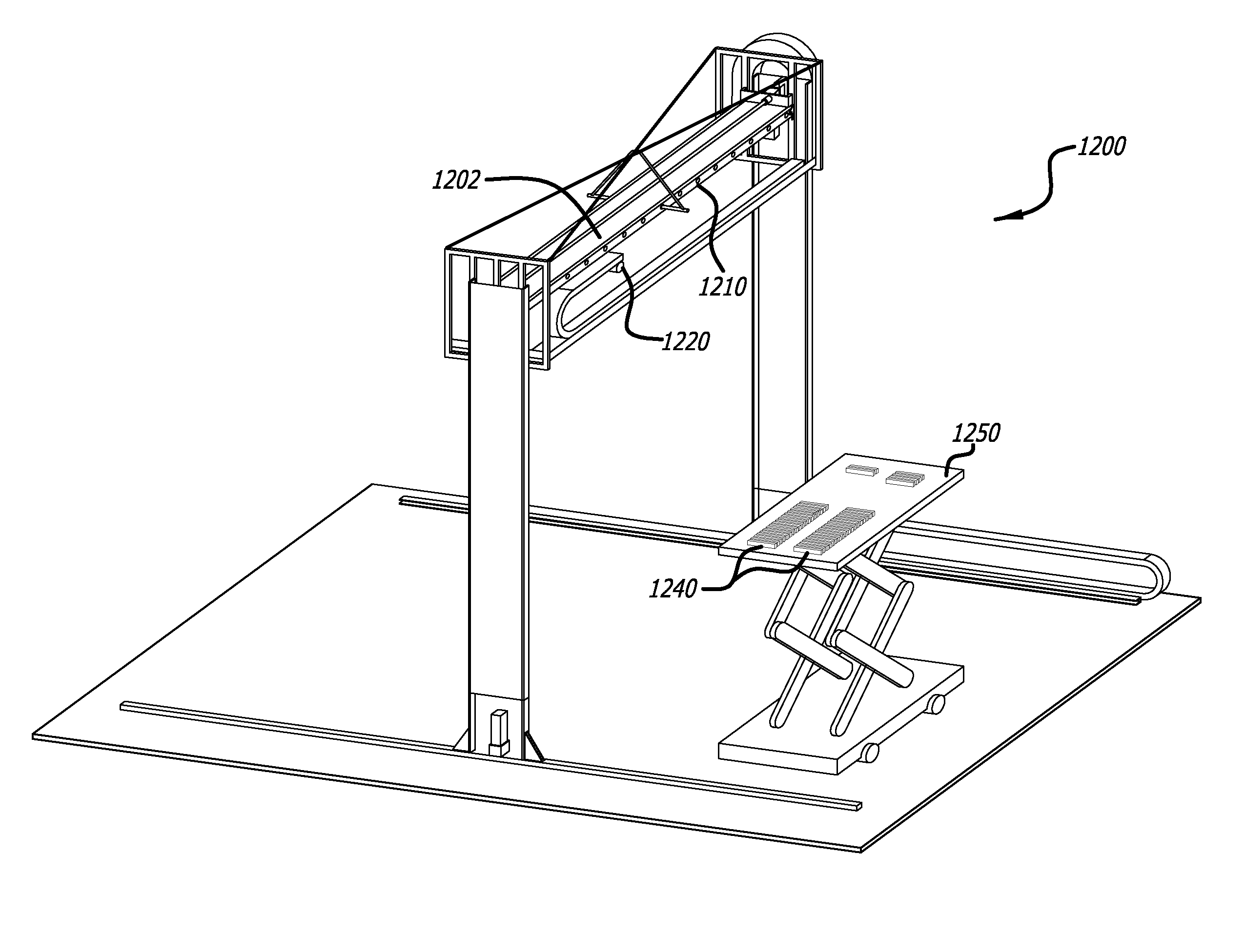
[0067]The articulated arm A-C could be mounted on an adjacent wall or on its own independent vertical truss 200 which could be installed at a corner of the work envelope of the robot (e.g., the North-East corner). The arm may have a desired number of segments, e.g., three segments (A+B+C), that are hinged together. These segments can collectively direct the hose from the material source to the nozzle on the robotic gantry system, e.g., system 100 of FIG. 1.

[0068]Segment A is hinged at H1 to the vertical truss 200 and can swing in a horizontal plane. This s...


PUM

PropertyMeasurementUnit
lengthaaaaaaaaaa
angleaaaaaaaaaa
weightaaaaaaaaaa

Abstract

Apparatus and methods are disclosed that are useful for robotic gantry systems that are lightweight while at the same time offering rigidity or stiffness for implementation in Contour Crafting construction and material delivery techniques. The present disclosure is directed to robotic gantry system and material transport apparatus that use of very light structural members that have sufficient compressive strength, but which may otherwise be weak in the presence of bending forces, in conjunction with cables that provide stiffness against bending. Use of such cables provides needed tension while at the same time allowing the robotic gantry system to be very light compared to solid structures, e.g., those with I-beams, etc. Material delivery systems including passive articulated arms are also disclosed.

Description

CROSS-REFERENCE TO RELATED APPLICATION[0001]This application claims priority to U.S. Provisional Patent Application Ser. No. 60 / 864,293, entitled “Gantry Robotics System and Related Material Transport for Contour Crafting,” filed Nov. 3, 2006, the contents of which are incorporated herein by reference in their entirety.GOVERNMENT INTEREST[0002]This invention was made with government support under Grant No. N000140510850, awarded by the Office of Naval Research. The government has certain rights in the invention.BACKGROUND[0003]Constructing homes, offices, boats and other structures has an ancient heritage. Despite all of the centuries of development, however, there can be difficulties and problems.[0004]Construction is usually very labor intensive. Even a modest size structure usually requires the efforts of numerous individuals. This can be very costly. Simultaneously using the time of numerous individuals in an efficient manner can also be challenging.[0005]The results of the cons...

Claims


Application Information

Patent Timeline
Patent Type & Authority Patents(United States)
IPC IPC(8): B28B19/00
CPCB05B13/04B23Q1/012B23Q11/0014B25J5/04B25J9/026B25J19/002
Inventor KHOSHNEVIS, BEHROKH
Owner UNIV OF SOUTHERN CALIFORNIA
Why Eureka
Try Eureka