Method and system for determining a position of a vehicle

a robotic vehicle and position technology, applied in the direction of distance measurement, instruments, and using reradiation, can solve the problems of slow execution or retrieval of random paths, and achieve the effect of facilitating execution or retrieval

Active Publication Date: 2011-10-04
DEERE & CO
View PDF16 Cites 57 Cited by
  • Summary
  • Abstract
  • Description
  • Claims
  • Application Information

AI Technical Summary

Problems solved by technology

However, if the vehicle is a mower, sprayer, or other device that is designed to cover all or a substantial portion of the work area, the execution of such random paths tends to be slow and energy inefficient.

Method used


Image

  • Method and system for determining a position of a vehicle
  • Method and system for determining a position of a vehicle
  • Method and system for determining a position of a vehicle

Examples


Embodiment Construction

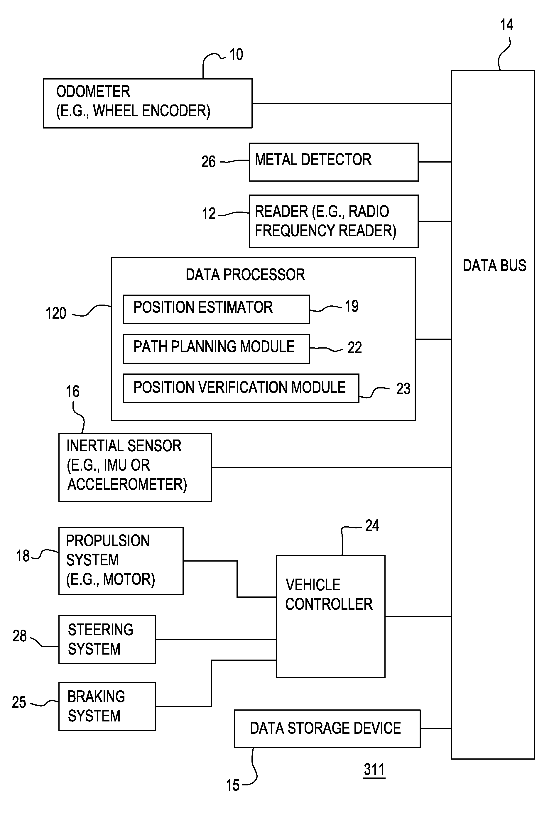
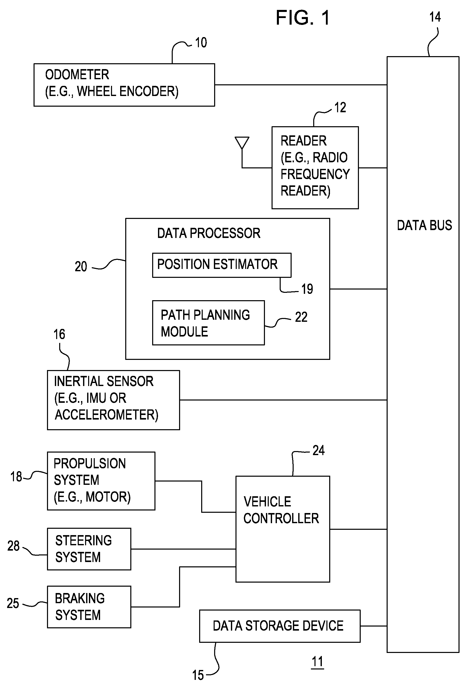
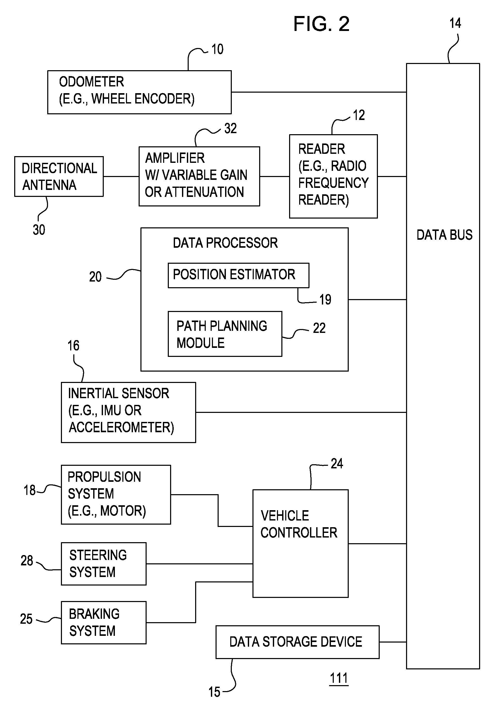
[0016]In FIG. 1, in accordance with one embodiment, a system 11 for determining position of a vehicle comprises an odometer 10, a reader 12, and an inertial sensor 16 that are capable of communicating sensor data to a data processor 20 via a data bus 14. Sensor data includes one or more of the following: odometer data, radio frequency identification tag data, and inertial data (e.g., accelerometer data). Inertial data is synonymous with inertial sensor data. The data processor 20 may communicate with a data storage device 15 and a vehicle controller 24, directly or indirectly through the data bus 14 as shown in FIG. 1. The vehicle controller 24 is coupled to a propulsion system 18, a braking system 25 and a steering system 28. The communication lines or paths interconnecting the vehicle controller 24 to the propulsion system 18, the braking system 25, and a steering system 28 may be routed through or connected to one another via a secondary data bus (not shown).

[0017]As illustrated ...


PUM


Abstract

Radio frequency identification tags are spaced apart from one another in or around a work area for the vehicle. Each of the tags has a corresponding unique identifier. A path planning module establishes a path comprising a path segment between at least two of the radio frequency identification tags. The path segment comprises at least one of a distance between the tags, an angular heading between the tags, and unique identifiers corresponding to the tags. A data processor determines an estimated position of the vehicle based on at least one of odometer data and accelerometer data. A vehicle controller navigates between at least two of the radio frequency identification tags based on the estimated position, the distance and the angular heading. A reader reads the tag identifiers of each tag to track the progress of the vehicle to facilitate execution of or retrieval of any next path segment of the vehicle along the established path.

Description

FIELD OF THE INVENTION[0001]This invention relates to a method and system for determining a position of a robotic vehicle.BACKGROUND[0002]In the prior art, a boundary of a work area may be defined by a buried wire, a cable, or conductor associated with an applied current (e.g., an alternating current). A vehicle for operation in the work area is equipped with a magnetic field detector or an electric field detector for detecting the magnetic or electric field generated by the boundary wire, cable, or conductor. If a magnetic or electric field is detected, a vehicle controller may instruct the vehicle to change its course to some random path within the work area. However, if the vehicle is a mower, sprayer, or other device that is designed to cover all or a substantial portion of the work area, the execution of such random paths tends to be slow and energy inefficient. Thus, there is a need for an alternative method and system for determining the position of the vehicle.SUMMARY OF THE...

Claims


Application Information

Patent Timeline
Patent Type & Authority Patents(United States)
IPC IPC(8): G08G1/123G01S13/931
CPCG01S13/825G01S13/931G05D1/028G05D1/0272G01S2013/9339G05D1/027G01S2013/9353G05D1/0274G01S2013/9342G01S2013/9346G05D1/0261G01S2013/9318G01S2013/9329G01S2013/93185G01S2013/932G05D2201/0208
Inventor THACHER, RUSSELL JAMESMOOREHEAD, STEWART J.DICKSON, MONTE ANDREFLENNIKEN, JOHN MICHAEL
Owner DEERE & CO
Why Eureka
Try Eureka