
Metropolitan area local access service system

a local access service and metropolis technology, applied in the field of fiber optic communications networks, can solve the problems of minor changes in infrastructure content, not end-user data content, and achieve the effect of surviving any single network failur

Inactive Publication Date: 2011-10-04
QWEST
View PDF37 Cites 2 Cited by
  • Summary
  • Abstract
  • Description
  • Claims
  • Application Information

AI Technical Summary

Benefits of technology

[0008]Layer 2, known as the bridging or switching layer, allows edge IP equipment addressing and attachment. It forwards packets based on the unique Media Access Control (“MAC”) address of each end station. Data packets consist of both infrastructure content, such as MAC addresses and other information, and end-user content. At Layer 2, generally no modification is required to packet infrastructure content when going between like Layer 1 interfaces, like Ethernet to Fast Ethernet. However, minor changes to infrastructure content—not end-user data content—may occur when bridging between unlike types such as FDDI and Ethernet. Additionally, the Ethernet service can inter-connect customers to create an “extended” LAN service.
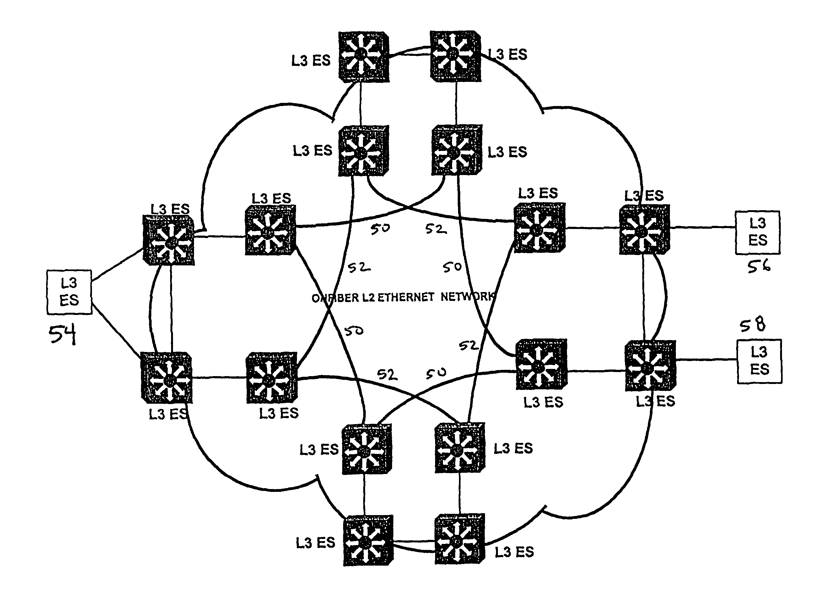
[0010]Embodiments of the present invention may include the following advantages: (1) in the BDN, a dedicated pair of diversely routed optical fibers for each customer; (2) in the core, a dual physical overlay ring core topology; (3) working and protection logical path connectivity; (4) no 802.1D Spanning Tree for recovery; (5) resilience to any single network failure in any device or link; (6) quick recovery times from failure relative to mechanisms based on Spanning Tree; and (7) a failure detection / recovery protocol that is not “active” on any devices other than the devices directly attached to the subscriber.

Problems solved by technology

However, minor changes to infrastructure content—not end-user data content—may occur when bridging between unlike types such as FDDI and Ethernet.

Method used


Image

  • Metropolitan area local access service system
  • Metropolitan area local access service system
  • Metropolitan area local access service system

Examples


second alternative embodiment

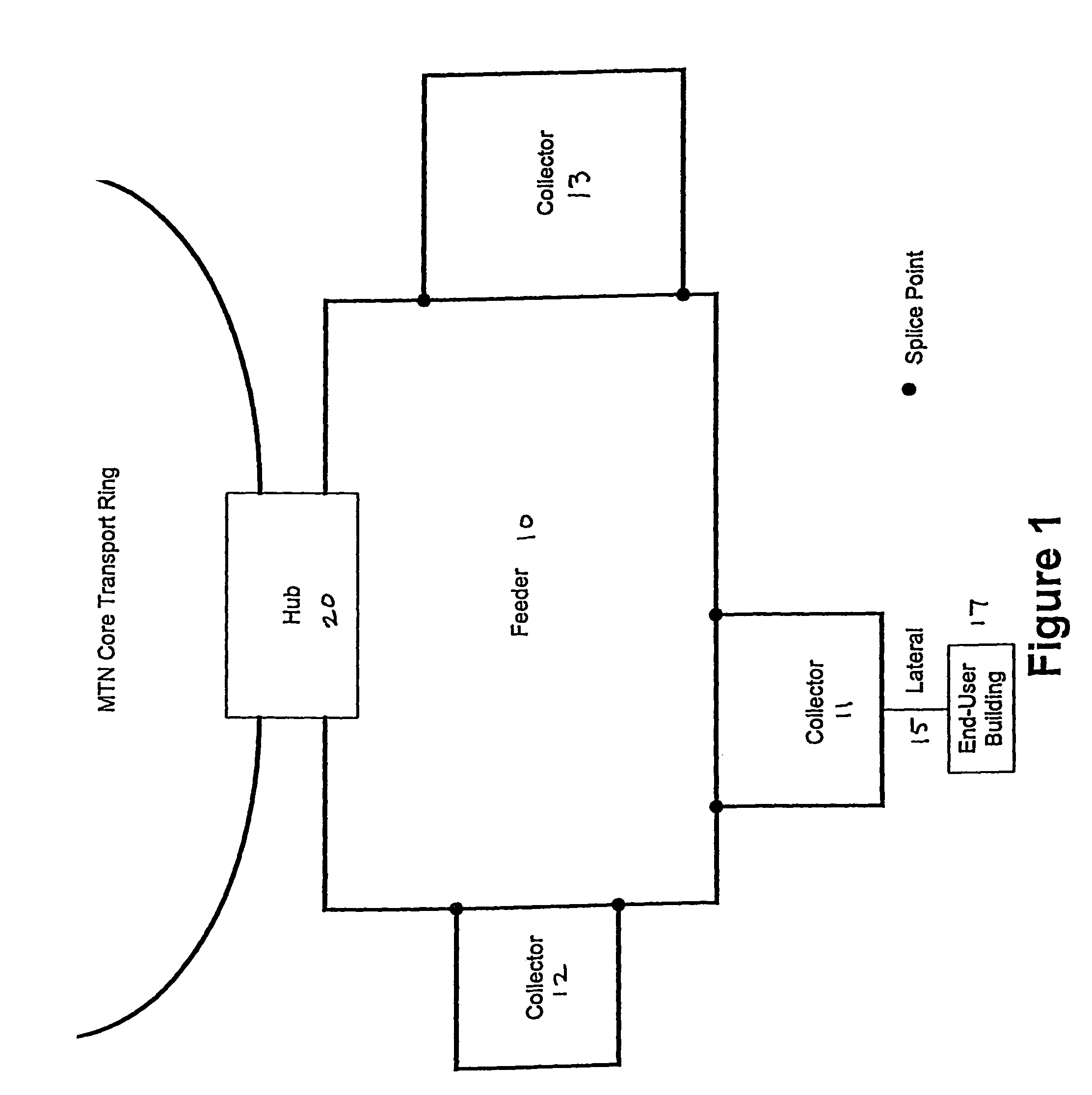
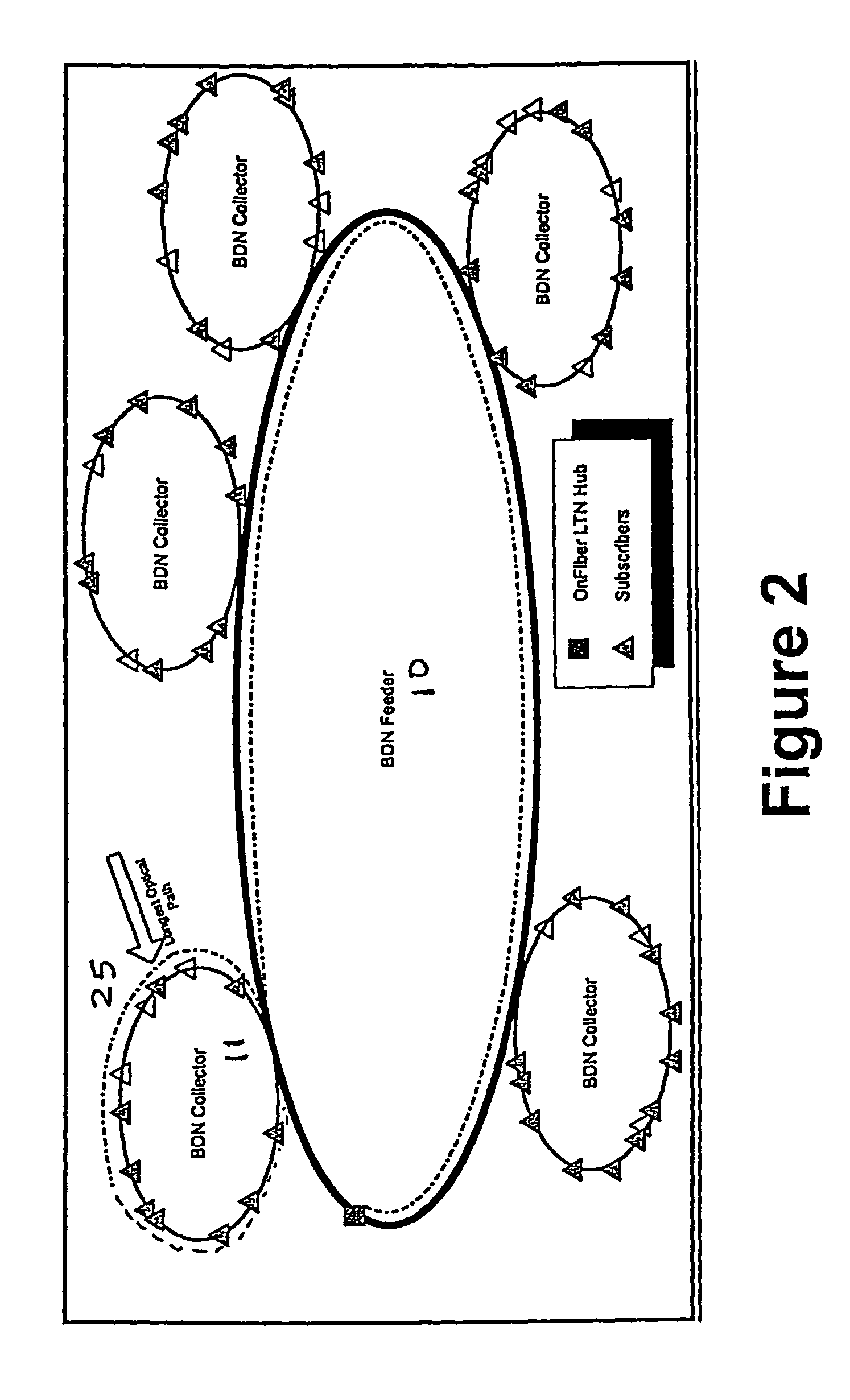
[0057]In this scenario, the distribution network provider deploys a pair of nested Feeder rings 30 in each distribution network. The collectors 31, 32 and 33 closest to the hub 20 are placed on the nested feeder 30, while the collectors 40, 41 and 42 located farther out are placed on the longer feeder 40. FIG. 3 displays a generic example of this configuration. With the FIG. 3 type of configuration, the longer feeder 40 can remain longer (e.g., more than 7 miles in circumference) without stranding capacity because the collectors closest to the LTN hub 20 have a shorter path available to them.

[0058]Although the additional cross-section of fiber that completes the interior Feeder may increase the cost of the distribution network, it may also provide the opportunity to place one or more additional Collectors that would have otherwise been difficult to attach to the single Feeder design.

[0059]Decision Rule for Distribution Network Variants

[0060]In significant part, the distribution netw...


PUM


Abstract

A local access fiber optical distribution network is disclosed in which a dedicated pair of diversely routed optical fibers is routed in the distribution network for each customer. In a preferred embodiment, a dual physical overlay ring core topology is used in the core. The distribution network includes working and protection logical path connectivity. No 802.1D Spanning Tree is required for recovery, providing resilience to any single network failure in any device or link, quick recovery times from failure, and a failure detection / recovery protocol that is not active on any devices other than the devices directly attached to the subscriber.

Description

CROSS REFERENCE TO RELATED APPLICATIONS[0001]This application is a divisional of U.S. Ser. No. 09 / 952,284, filed on Sep. 12, 2001.FIELD OF THE INVENTION[0002]The invention generally relates to the field of fiber optic communications networks, and more particularly to a new system and method for deploying and operating a metropolitan area local access distribution network.RELATED ART[0003]The growth of the Internet has created unprecedented demand for high-speed broadband connectivity in telecommunications networks. However, access connections between corporate Local Area Networks (“LANs”) and existing service provider networks, such as those operated by long-haul carriers and Internet Service Providers (“ISPs”), generally have been limited to relatively slow, hard to provision T1 (1.5 Mbps) or DS-3 (45 Mbps) data speeds due to infrastructure limitations in most metropolitan areas.[0004]The lack of bandwidth throughout metropolitan areas is a function, principally, of two independent...

Claims


Application Information

Patent Timeline
Patent Type & Authority Patents(United States)
IPC IPC(8): G01R31/08H04L12/28H04L12/46H04L12/56H04L69/40H04Q11/00
CPCH04L12/2852H04L12/4637H04L49/357H04L69/40H04L49/351H04L49/354H04L49/602H04Q11/0067H04Q11/0071H04Q2011/0073H04Q2011/0081
Inventor GUESS, MICHAELNIEZGODA, PAULSTREET, FRASER
Owner QWEST
Learn More