
Retroreflective structures having a helical geometry

a technology of helical geometry and retroreflective structure, which is applied in the field of retroreflective structure having a helical geometry, can solve the problems of low retroreflectivity of retroreflectors, limited configuration, and low protection against abrasion and degradation of retroreflectors, and achieves superior retroreflectivity, improved retroreflection, and appearance and wet-weather performan

Inactive Publication Date: 2011-10-11
TECH SOLUTIONS & INVENTION
View PDF9 Cites 12 Cited by
  • Summary
  • Abstract
  • Description
  • Claims
  • Application Information

AI Technical Summary

Benefits of technology

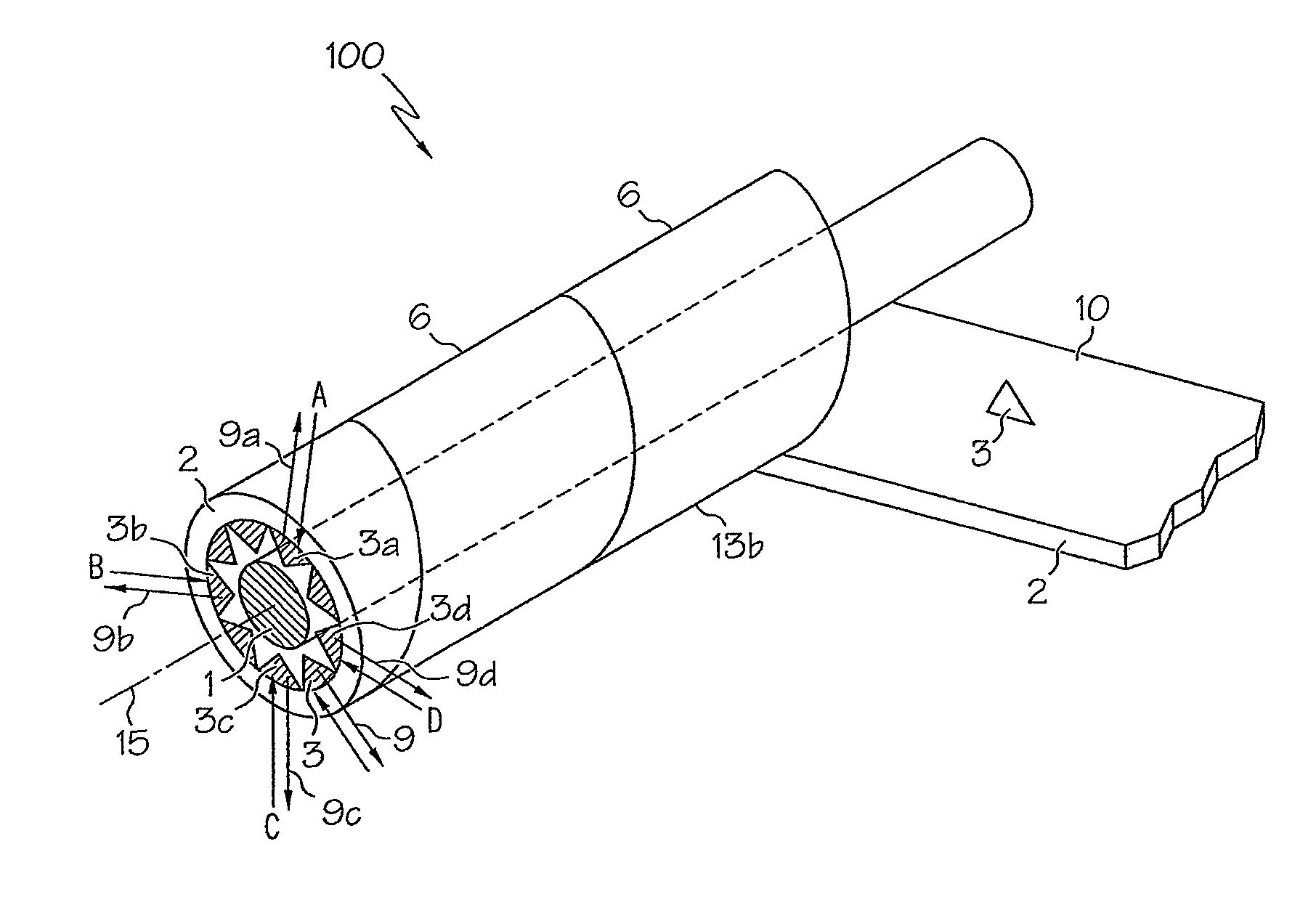
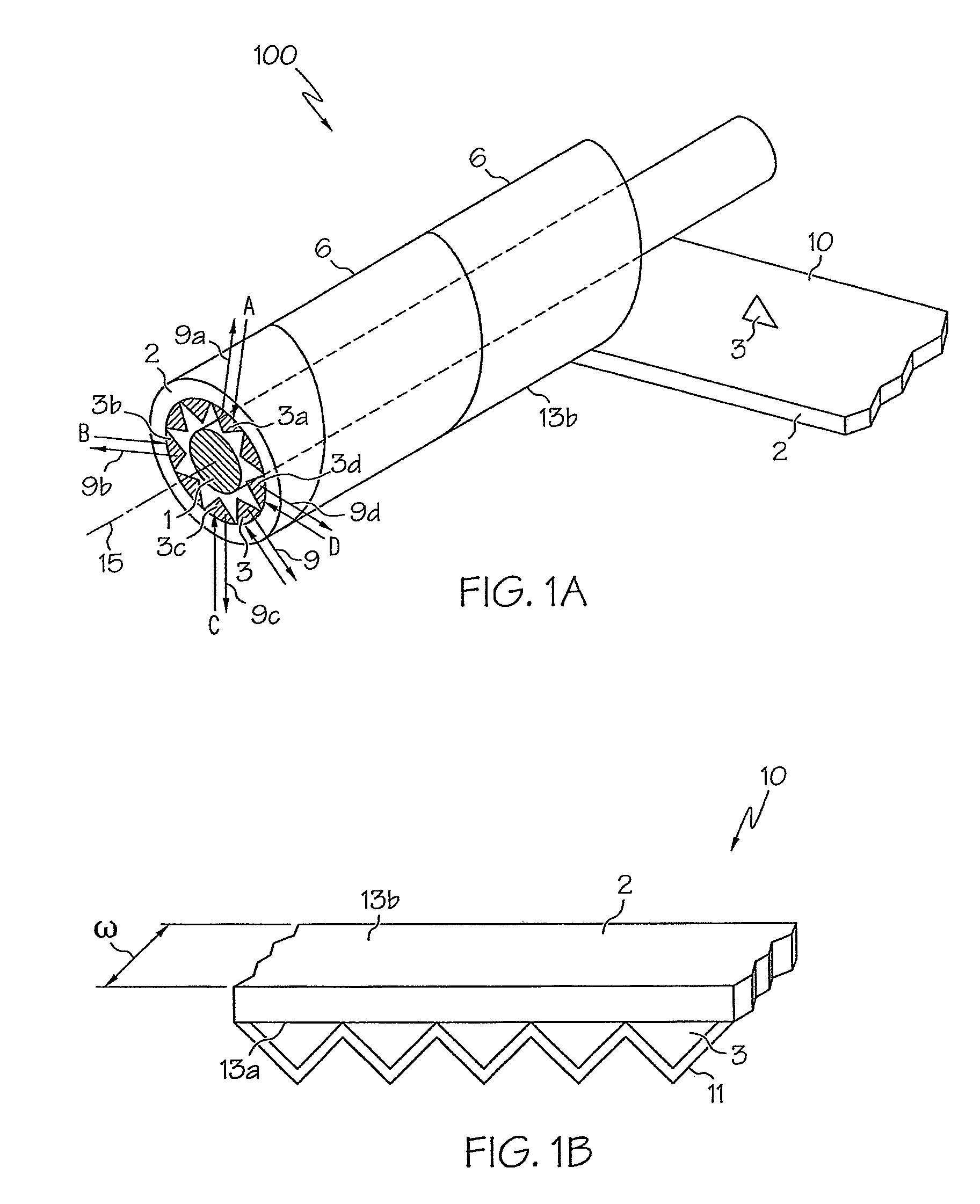
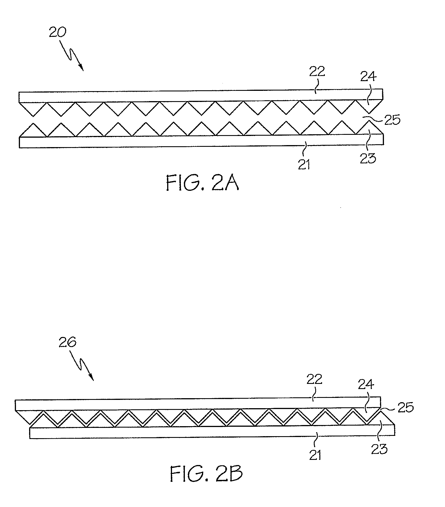
"The present patent is about improving retroreflective structures by using a helical path and a plurality of retroreflective optical elements. The retroreflective optical elements can be positioned along the helical path and can include corner cube structures, resonant structures, or other types of retroreflective optical elements. The body of material in which the optical elements are positioned can be at least partially transparent to incident electromagnetic energy. The retroreflective structure can also include a reflective coating on the optical elements, a hollow core, an upper layer, or other features. The technical effects of this patent include improved retroreflection, appearance, and wet-weather performance of the retroreflective structures."

Problems solved by technology

However, since a fiber, thread, yarn, and the like has glass bead retroreflectors exposed on its surface, this configuration offers little protection against abrasion and degradation of the retroreflectors.
Further, the fabrics and materials to which the retroreflectors are attached tend to have low levels of retroreflectivity, and the retroreflectors themselves have limited life expectancies with regard to effectiveness.
Also, exposed glass bead retroreflectors can also abrade textile manufacturing equipment, and can also degrade the fabric material to which the retroreflectors are attached.
In addition, exposed glass bead retroreflectors can lose their retroreflective properties when wet.
In addition, conventional glass retroreflectors or lenses are randomly attached to the fabrics and materials, and are of different and random shapes and sizes, further reducing the effectiveness of the retroreflectors.
However, conventional retroreflective fibers include non-retroreflecting edges, which can change the appearance of the fiber.
In addition, such conventional retroreflective fibers do not include a reinforcing inner layer, causing the fibers to be insufficiently fragile.
As such, it is undesirable to use conventional retroreflective fibers to form fabrics by sewing, knitting, embroidering, and the like.

Method used


Image

  • Retroreflective structures having a helical geometry
  • Retroreflective structures having a helical geometry
  • Retroreflective structures having a helical geometry

Examples


Embodiment Construction

[0069]Embodiments of the present invention will now be described more fully hereinafter with reference to the accompanying drawings, in which preferred embodiments of the invention are shown. This invention may, however, be embodied in different forms and should not be construed as limited to the embodiments set forth herein. Like numbers refer to like elements throughout the specification.

[0070]It will be understood that, although the terms first, second, etc. are used herein to describe various elements, these elements should not be limited by these terms. These terms are used to distinguish one element from another. For example, a first element could be termed a second element, and, similarly, a second element could be termed a first element, without departing from the scope of the present invention. As used herein, the term “and / or” includes any and all combinations of one or more of the associated listed items.

[0071]It will be understood that when an element is referred to as b...


PUM


Abstract

Retroreflective structures and methods of forming the same comprise a body of material extending along a helical path about a longitudinal axis and a plurality of retroreflective optical elements positioned along the helical path of the body of material, and constructed and arranged to retroreflect electromagnetic energy directed from a range of angular orientations about the longitudinal axis.

Description

RELATED APPLICATIONS[0001]This application claims the benefit of U.S. Provisional Patent Application No. 60 / 955,235, filed Aug. 10, 2007, and U.S. Provisional Patent Application No. 61 / 031,195, filed Feb. 25, 2008, the content of each being incorporated herein by reference in its entirety.BACKGROUND OF THE INVENTION[0002]Conventional retroreflective fibers, threads, yarns, and the like that are used in fabrics are generally formed using a binder to attach glass bead retroreflectors to the surface of natural or synthetic fibers from which the threads, yams, and the like are formed. However, since a fiber, thread, yarn, and the like has glass bead retroreflectors exposed on its surface, this configuration offers little protection against abrasion and degradation of the retroreflectors. Further, the fabrics and materials to which the retroreflectors are attached tend to have low levels of retroreflectivity, and the retroreflectors themselves have limited life expectancies with regard t...

Claims


Application Information

Patent Timeline
Patent Type & Authority Patents(United States)
IPC IPC(8): G02B5/122
CPCG02B5/124Y10S359/90
Inventor NILSEN, ROBERT B.NILSEN, GARRETT L.
Owner TECH SOLUTIONS & INVENTION
Learn More