Safety device, diving equipment and safety method for scuba diving

a safety device and diving equipment technology, applied in life-saving devices, underwater equipment, inhalators, etc., can solve the problems of diver throwing, he will soon start to sink below the surface, and the diver's common and irrational behaviour, so as to improve the safety method

Active Publication Date: 2011-10-11
SCUBATECH SWEDEN AB
View PDF10 Cites 5 Cited by
  • Summary
  • Abstract
  • Description
  • Claims
  • Application Information

AI Technical Summary

Benefits of technology

[0011]Thanks to the invention, a diver that would otherwise risk drowning will be safely brought up to the water surface. By the method being based on sensing whether the diver breathes in his breathing regulator, the safety device can be arranged to initiate inflation of the diving jacket in situations in which normal safety systems would not detect the emergency, for example if the diver is apparently under control close to the water surface but without breathing in his breathing regulator (for a certain predefined time), which could for example be the case due to heart problems.
[0012]In a preferred embodiment, the safety device is operated by air from the pressure tank, which means that the safety device will have high reliability. A preferred device according to the invention is also characterised in that it is affected only by a few components that are suitably known per se at the market, whereby product costs can be kept down. According to a preferred embodiment, the safety device is easy to connect to existing diving equipment or it can be integrated in new equipment, for example at the connection of the pressure tank to the jacket or integrated in a dive computer. Thereby, safety in connection with SCUBA diving can be considerably improved in a flexible way and at a relatively reasonable cost. By being able to use the invention in principle in combination with existing equipment independent of the make, a diver may continue to use the equipment that he is most comfortable with, resulting in additional synergy in respect of safety.
[0016]Additional aspects of the invention are clear from the additional dependent claims and from the description.
[0017]In addition to this, the safety method and the safety device according to the invention should also contribute to the achievement of one, some or preferably most of the objects listed below:
[0018]the safety device can be installed on existing diving equipment,
[0020]the safety device should have high reliability,
[0011]Thanks to the invention, a diver that would otherwise risk drowning will be safely brought up to the water surface. By the method being based on sensing whether the diver breathes in his breathing regulator, the safety device can be arranged to initiate inflation of the diving jacket in situations in which normal safety systems would not detect the emergency, for example if the diver is apparently under control close to the water surface but without breathing in his breathing regulator (for a certain predefined time), which could for example be the case due to heart problems.
[0023]manual setting of the actuation zone depth,
[0024]when diving in shallow water (not more than 3-5 m), in connection with training e.g., the safety system can be continuously active, which will lead to improved safety for inexperienced divers,
[0025]manual actuation of the safety system can be offered, which could be an advantage in connection with training in which the safety system can be actuated already on land for training purposes as well as from a safety point of view,
[0026]actuation by remote control can be offered, e.g. in combination with a dive computer, wireless transmission / reception,
[0027]the safety system can be connected to (or be integrated in) a dive computer.

Problems solved by technology

If for example the diver surfaces after an ascent and for some reason he is under stress, a common and irrational behaviour is that the diver throws out his breathing regulator directly, despite having been taught first to secure buoyancy.
If the diver then fails to secure buoyancy at surface by inflating the diving jacket, he will soon start to sink below the surface again since the diving equipment has weights to help the diver to stay under water.
The diver will then sink very rapidly due to the weight of the diving equipment.

Method used


Image

  • Safety device, diving equipment and safety method for scuba diving
  • Safety device, diving equipment and safety method for scuba diving
  • Safety device, diving equipment and safety method for scuba diving

Examples


Embodiment Construction

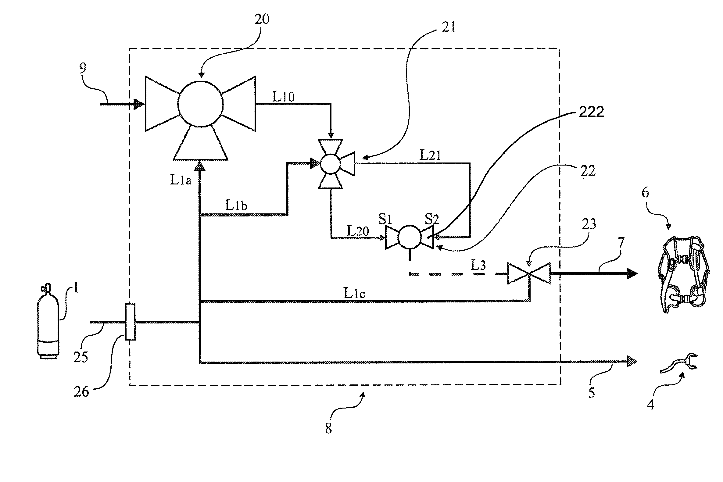
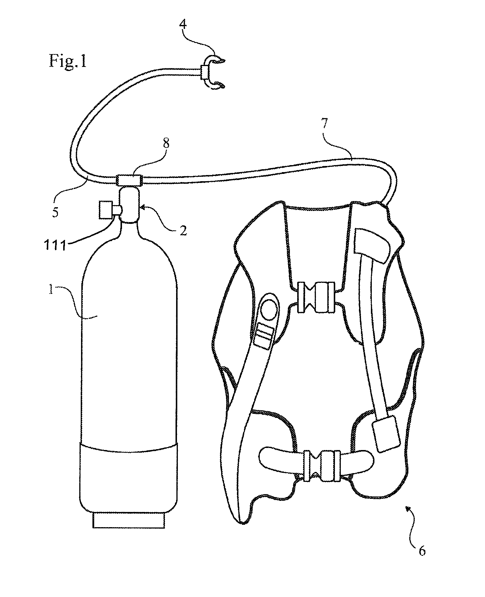
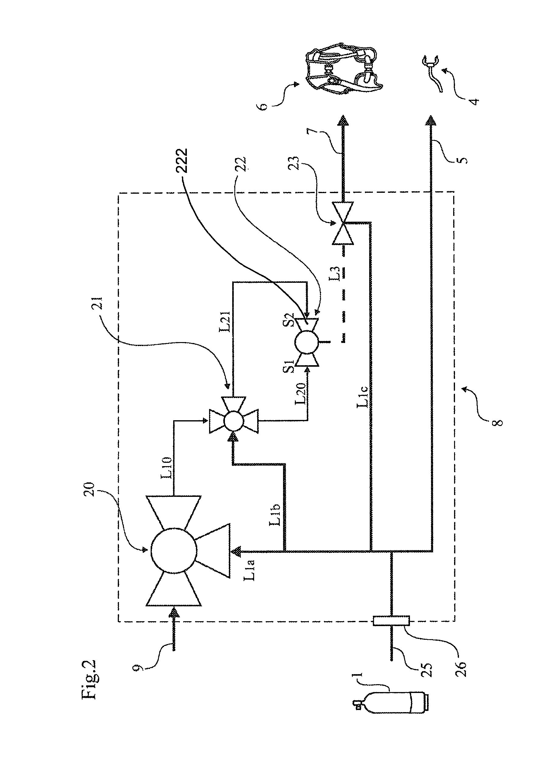
[0034]FIG. 1 shows a set of diving equipment used in connection with SCUBA diving. The equipment comprises at least one pressure tank 1, a valve device 2 connected to the pressure tank and arranged to supply air from said pressure tank via a first flexible tube 5 to a breathing regulator 4. The valve device 2 is also arranged to supply air from the pressure tank to a so called diving jacket 6. The diving jacket 6, which is inflatable, is carried by the diver and it is used to control his buoyancy. The diving jacket 6 is supplied with air via a second flexible tube 7 from the pressure tank. The diving equipment further comprises an actuator 8 that is arranged to communicate with said valve device 2 in order to initiate inflation of the diving jacket 6. Suitably, the actuator 8 is connected with the valve device 2 such that the connection them between is flexible, e.g. in the form of an intermediate elastic tube means (not shown) that allows for a certain pliability with the purpose o...


PUM


Abstract

The present invention relates to a method in connection with SCUBA diving to control a diver's buoyancy, in which method the diver (11) is equipped with diving equipment comprising at least one air pressure tank (1), a valve device (2) connected to the pressure tank (1) and arranged to supply air from said pressure tank via first supply means (5) to a breathing regulator (4) and via second supply means (7) to an inflatable diving jacket (6) in order to control the diver's buoyancy, inflation of the diving jacket being initiated when the diver has not affected the air flow through the breathing regulator (4) for a certain time period. The invention also relates to a safety device and diving equipment.

Description

CROSS-REFERENCE TO RELATED APPLICATIONS[0001]This application is a national stage entry under 35 U.S.C. 371 of International Application No. PCT / SE2006 / 050493, filed 20 Nov. 2006, designating the United States. This application claims foreign priority under 35 U.S.C. 119 and 365 to Swedish Patent Application No. 0502557-2, filed 18 Nov. 2005.TECHNICAL FIELD[0002]The present invention relates to a safety device, diving equipment and a safety method in connection with SCUBA diving, for controlling a diver's buoyancy, in which the diver is equipped with diving equipment comprising at least one air pressure tank, a valve device connected to the pressure tank and arranged to supply air from said pressure tank via a first flexible tube to a breathing regulator and via a second flexible tube to a partially inflatable diving jacket in order to control the diver's buoyancy, and an actuator arranged to communicate with said valve device in order to initiate inflation of the diving jacket. Mor...

Claims


Application Information

Patent Timeline
Patent Type & Authority Patents(United States)
IPC IPC(8): B63C11/02
CPCB63C11/08B63C11/2245B63C2011/085
Inventor STOOD, JANPATRIKSSON, OLAVAN OOSTRUM, CHRISTIANERDTMAN, THOMAS
Owner SCUBATECH SWEDEN AB
Why Eureka
Try Eureka