Distortion compensation

a technology of distortion compensation and amplifier, applied in the field of distortion compensation in amplifiers, can solve the problems of affecting the perceived sound quality of the amplifier, the audio signal of the amplifier will be distorted, and the control of distortion for each channel, so as to achieve the effect of increasing the perceived sound quality

Active Publication Date: 2011-10-11
HARMAN INT IND INC
View PDF134 Cites 34 Cited by
  • Summary
  • Abstract
  • Description
  • Claims
  • Application Information

AI Technical Summary

Benefits of technology

[0008]A system controls or compensates for audio distortion based on a supply voltage, such as the voltage supplied by the battery of an automobile. A signal related to the supply voltage is used to control the gain, and distortion, of an audio signal. In an example, the supply voltage signal is used to control a threshold level that determines whether the audio signal may be clipped. Using the supply voltage provides for control of distortion, increasing the perceived sound quality.
[0009]A clipping threshold may be adjusted according to a supply voltage signal. An audio amplifier may be tuned to have a pre-determined clipping threshold, or tuned threshold based on the supply voltage at the time of tuning. A signal associated with the supply voltage can be used to determine an adjustment to the tuned threshold to provide an applied threshold. As the battery voltage decreases, the signal associated with the decreased battery voltage decreases the tuning threshold by an appropriate amount to decrease the applied threshold. When the battery voltage increases, the tuned threshold may be increased accordingly to maximize the amplifier operation. Accordingly, the threshold may be modified according to the supply voltage to maintain a fixed level of distortion and maximize power output.

Problems solved by technology

If the voltage in the vehicle is insufficient for the amplifier to accurately amplify the input signal, the amplifier may clip, and the audio signal from the amplifier will be distorted.
Since clip detection of monolithic power amplifier integrated circuits is typically shared over two or more channels, the analog control maintains a relatively constant amount of distortion, but may not control the distortion for each channel independently.
Accordingly, hard-coded distortion limiting using a DSP may not provide an optimal amplification of the audio signal for a wide range of battery supply voltages.

Method used


Image

  • Distortion compensation
  • Distortion compensation
  • Distortion compensation

Examples


Embodiment Construction

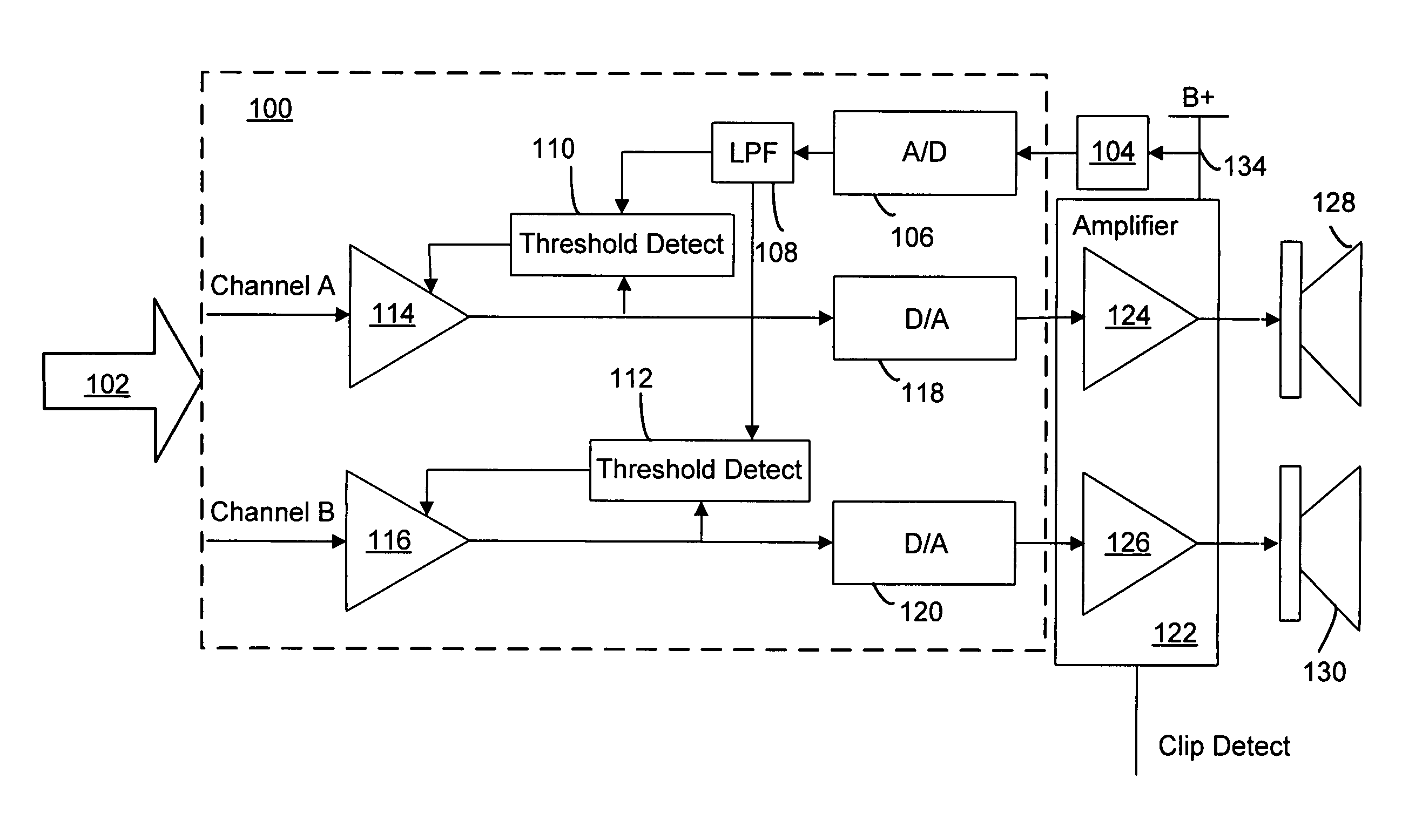
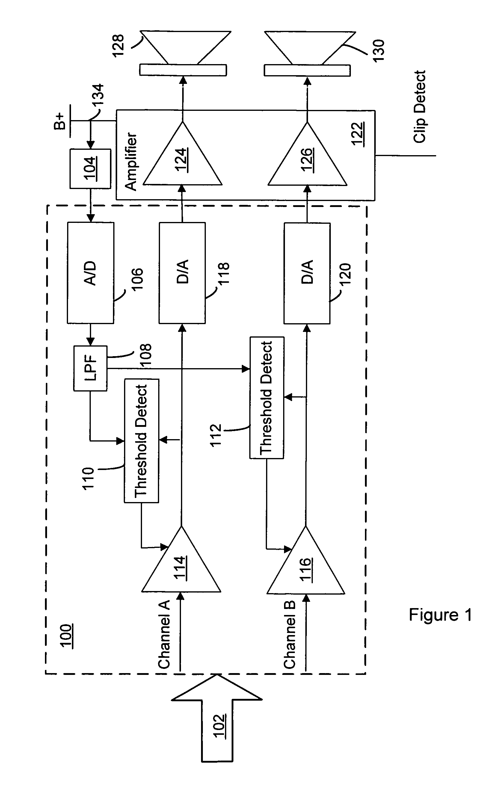
[0020]A distortion compensation system minimizes audio distortion by monitoring a supply voltage. In the figures, components, features and integral parts that correspond to one another each have the same reference number. The figures are not true to scale.

[0021]The distortion compensation system may by used with an automotive or vehicle audio system. A distortion compensation system may be a component or a unitary part of an audio amplifier for the automotive audio system. The audio amplifier is powered by a rail voltage supplied by the automotive battery. The rail voltage may fluctuate within an operating range typically from around 9 Volts to around 14 Volts. The rail voltage is compared or measured against a reference voltage, which may be a tuning voltage. A signal representative of the comparison, or measurement, is generated. The signal is sent to a controller that processes the multi-channel audio signal for the audio system. The controller controls gain of an audio signal ba...


PUM


Abstract

A distortion compensation system minimizes distortion in an audio system by monitoring a supply voltage and adjusting a clipping threshold and / or compression knee. An adjustable gain circuit controls the gain of the audio signal according whether the audio signal exceeds a variable threshold. The variable threshold is adjusted within a threshold range based on the supply voltage. Distortion due to clipping of the audio signal is minimized while available power at any given time is maximized.

Description

BACKGROUND OF THE INVENTION[0001]1. Technical Field[0002]The invention relates to audio amplifiers, and particularly to distortion compensation in amplifiers for vehicle audio systems.[0003]2. Related Art[0004]Automotive audio systems include one or more amplifiers that provide gain for audio signals. The gain of an amplifier depends, at least in part, on the amount of power supplied to the amplifier. Because the supply voltage varies over a range of several volts, the amount of power that is available to the amplifier will also vary over a wide range. If the voltage in the vehicle is insufficient for the amplifier to accurately amplify the input signal, the amplifier may clip, and the audio signal from the amplifier will be distorted. Accordingly, amplifiers may be designed to control audio output according to fluctuations, or variations, in the limits of the battery supply voltage, or minimum expected available power.[0005]To preclude the amplifier from being overdriven, an amplif...

Claims


Application Information

Patent Timeline
Patent Type & Authority Patents(United States)
IPC IPC(8): H03F99/00
CPCH03F1/32H03G11/008H03G3/007H03G7/004H03F2200/03H03F2200/321H03F2200/471H03F2200/78H03F2200/66
Inventor FURGE, KENNETH CARL
Owner HARMAN INT IND INC
Why Eureka
Try Eureka