Stress free mounting of optical bench for WSS

a technology of stress-free mounting and optical benches, which is applied in the direction of optical waveguide light guides, instruments, optics, etc., can solve the problems of increasing the cost of assembly, affecting the assembly efficiency of the optical bench, and affecting the mechanical packaging of the optical bench

Active Publication Date: 2011-10-11
LUMENTUM OPERATIONS LLC
View PDF17 Cites 20 Cited by
  • Summary
  • Abstract
  • Description
  • Claims
  • Application Information

AI Technical Summary

Benefits of technology

[0009]In accordance with one embodiment of the invention there is provided a wavelength selective switch comprising a housing having a base, sidewalls and a cover; optical input and output ports for receiving input optical signals and transmitting output optical signals; an optical bench for supporting a plurality of optical components including a dispersion element for dispersing the input optical signals into individual wavelength channels and for combining selected groups of the wavelength channels into the output optical signals, and lensing elements for collimating and focusing the input, output and dispersed optical signals; an array of switching elements mounted on the base of the housing for redirecting the dispersed wavelength channels to selected output ports; wherein the optical bench is connected to the base of the housing at three attachment points; wherein the attachment point nearest the array of switching elements is a fixed attachment point to substantially restrict any relative movement between the optical components on the optical bench and the switching elements; and wherein the other two attachment points are flexible attachment points to enable relative movement between the optical bench and the base of the housing, thereby accommodating for differences in thermal expansion coefficients between the optical bench and the housing.

Problems solved by technology

Unfortunately, due to the relatively large footprint of the free-space optics, and due to the large number of electrical connections to the optical switching engine, mechanical packaging of WSSs represents a considerable technical challenge.
Unfortunately, it takes a long time and considerable operator skill and effort to fit all the fiber feed-through, flex-PCBs, and to fit and align the optical elements inside the package, which increases the cost of the assembly and reduces manufacturing yields.
Furthermore, a WSS enclosure built using this technology has a relatively large footprint since the optics, the flex-PCB, and the multi-pin hermetic connector need to be accommodated inside the package.
The large size of prior art WSS enclosures is considered a drawback because telecom system providers are strongly motivated to increase the element density of their circuit cards, to facilitate a decrease in the system size and cost.

Method used


Image

  • Stress free mounting of optical bench for WSS
  • Stress free mounting of optical bench for WSS
  • Stress free mounting of optical bench for WSS

Examples


Embodiment Construction

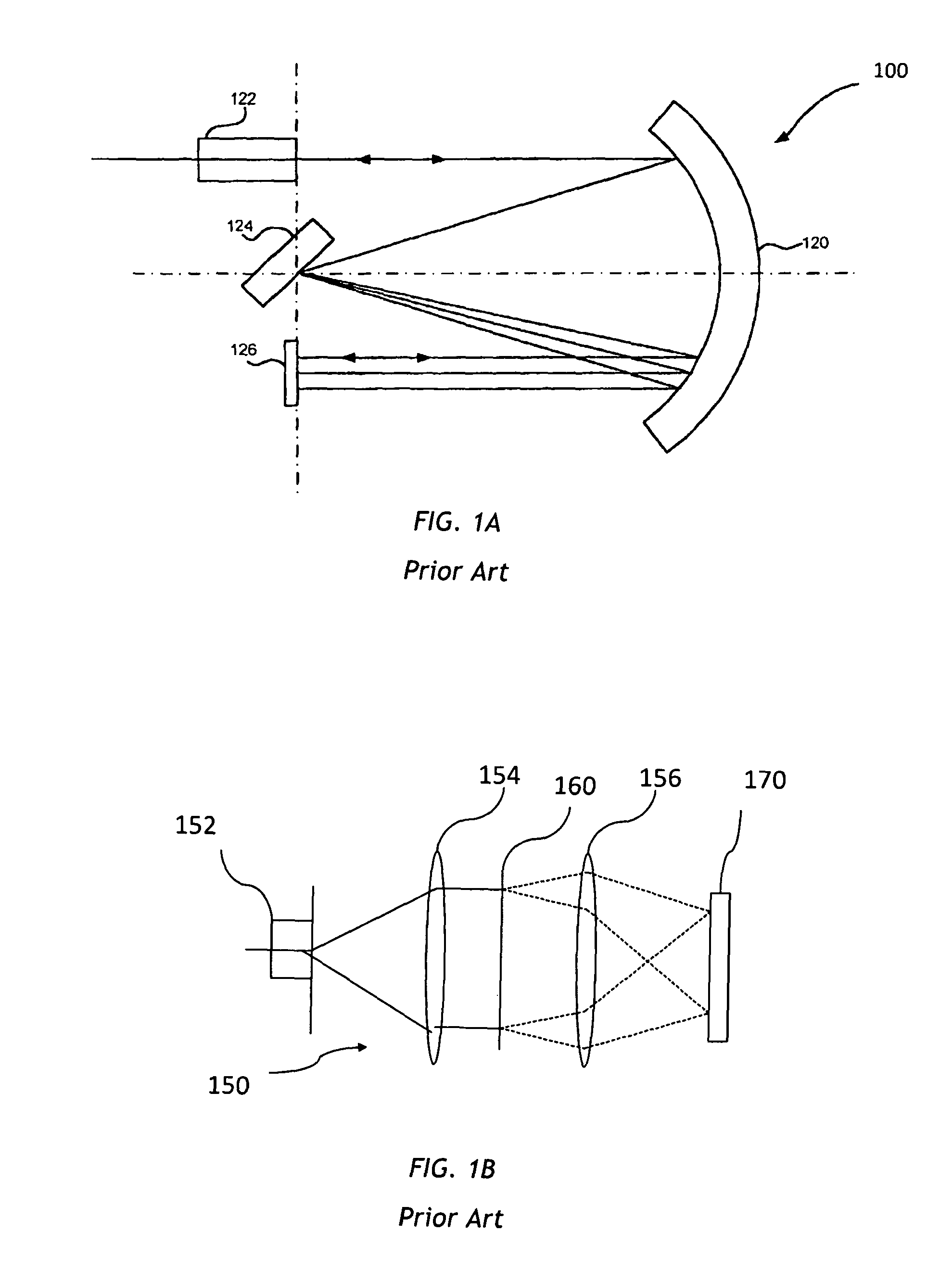
[0029]Referring to FIG. 1A one example of a prior-art WSS is shown. The WSS 100 includes a front end 122 for launching and receiving free-space optical beams having a plurality of wavelength channels, a concave mirror 120 for focusing and collimating optical beams, a dispersive element 124 for spatially dispersing an input optical beam into the wavelength channels, and for combining the wavelength channels into an output optical beam, and an optical switching engine 126 for selectively switching individual wavelength channels from an input optical port to an output optical port (not shown), wherein both ports are optically coupled to the front end 102. In one embodiment, the dispersive element 124 is a diffraction grating and the optical switching engine 126 is a micro-electro-mechanical system (MEMS) micromirrors array. In another embodiment, the optical switching engine 126 is a liquid crystal (LC) array, such as a liquid crystal on silicon (LCOS) array.

[0030]In operation, an inpu...


PUM


Abstract

An optical bench in a wavelength selective switch (WSS) is mounted using a combination of fixed mounts and stress-free mounts. The WSS is packaged in an enclosure including a base, a sidewall, and a lid. The optical switching engine is attached directly to the base. The optical bench is attached to the base and the optical components supported thereon are aligned with the array of switching elements of the switching engine. The optical bench is attached to the base with at plurality of mounts, which include at least one movable mount supporting movement of the optical bench in a plane parallel to the optical bench and at least one fixed mount maintaining optical alignment between the dispersive element and the array of switching elements.

Description

CROSS-REFERENCE TO RELATED APPLICATIONS[0001]The present invention claims priority from U.S. Provisional Application No. 61 / 045,648 filed Apr. 17, 2008, which is incorporated herein by reference.TECHNICAL FIELD[0002]The present invention is related to optical bench mounting, and in particular to the stress-free mounting of an optical bench in a wavelength selective switch (WSS).BACKGROUND[0003]In an optical communication network, optical signals having a plurality of optical channels at individual wavelengths, called “wavelength channels”, are transmitted from one location to another, typically through a length of optical fiber. An optical cross-connect module allows switching of optical signals from one optical fiber to another. A wavelength-selective optical cross-connect module, or a reconfigurable optical add-drop module (ROADM), allows wavelength-dependent switching, that is, it allows certain wavelength channels to be switched from a first optical fiber to a second optical fib...

Claims


Application Information

Patent Timeline
Patent Type & Authority Patents(United States)
IPC IPC(8): G02B6/35G02B6/26G02B6/28G02B6/12
CPCG02B6/3512G02B6/356G02B6/3582G02B6/29311G02B6/29313
Inventor DURICIC, NENADMCLAUGHLIN, SHELDONWALL, PIERRE D.
Owner LUMENTUM OPERATIONS LLC
Why Eureka
Try Eureka