Power over ethernet connector with integrated power source equipment (PSE) controller supporting high power applications

a technology of power over ethernet and integrated controller, which is applied in the direction of power supply for data processing, instruments, measurement devices, etc., can solve the problem that newer pds require substantially more power

Active Publication Date: 2011-10-11
AVAGO TECH INT SALES PTE LTD
View PDF8 Cites 49 Cited by
  • Summary
  • Abstract
  • Description
  • Claims
  • Application Information

AI Technical Summary

Problems solved by technology

However, some newer PDs require substantially more power (e.g. high power applications), including newer IP phones, access points, and video cameras.

Method used


Image

  • Power over ethernet connector with integrated power source equipment (PSE) controller supporting high power applications
  • Power over ethernet connector with integrated power source equipment (PSE) controller supporting high power applications
  • Power over ethernet connector with integrated power source equipment (PSE) controller supporting high power applications

Examples


Embodiment Construction

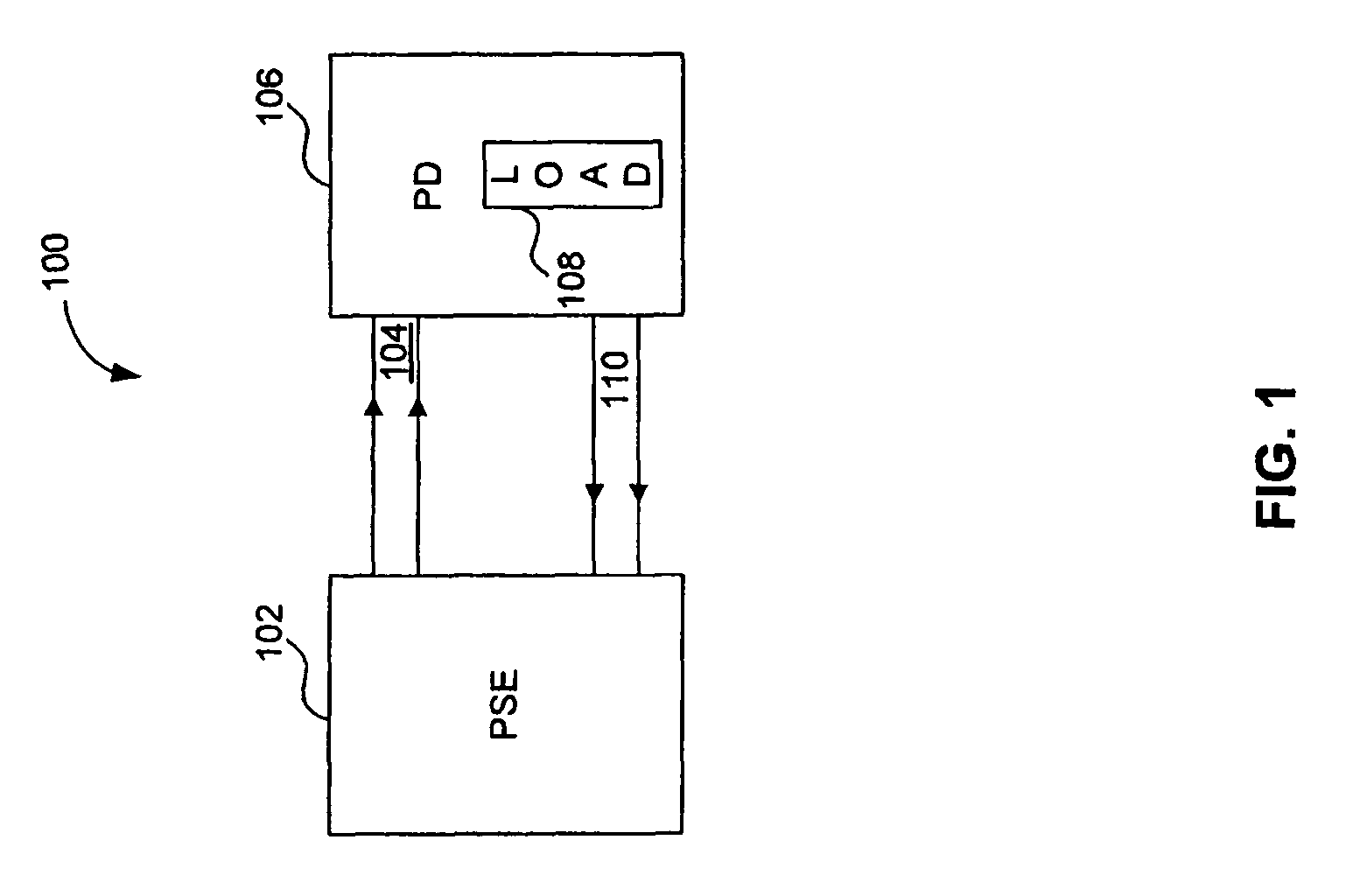
[0021]FIG. 1 illustrates a high level diagram of a conventional Power over Ethernet (PoE) system 100 that provides DC power over a common data communications medium. Referring to FIG. 1, power source equipment 102 provides DC power over conductors 104, 110 to a powered device (PD) 106 having a representative electrical load 108. Accordingly, the power transfer between the PSE 102 and the PD 106 occurs simultaneously with the exchange of high speed data over the conductors 104, 110. In one example, the PSE 102 when used with a switching and PHY chip is a data switch having multiple ports that is communicating with one or more PD devices, such as Internet phones, wireless access points, etc.

[0022]The conductor pairs 104 and 110 can carry high speed differential data communications. In one example, the conductor pairs 104 and 110 each include one or more twisted wire pairs, or any other type of cable or communications media capable of carrying the data transmissions and DC power transm...


PUM


Abstract

In a Power over Ethernet (POE) system, a power source equipment (PSE) device configured to deliver power to one or more powered devices (PDs) over a plurality of Ethernet transmission lines. The PSE interface includes a multi-port transmission line connector capable connecting to multiple Ethernet transmission lines, and a power source equipment (PSE) controller module integrated with the multi-port transmission line connector. The PSE controller module is capable of high power operation beyond that specifically by IEEE standard 802.3af™ for powered devices. More specifically, the PSE controller is configured to deliver over 15.4 Watts, and up to 36 Watts of power, to meet the needs of high powered devices such as IP Phones, and access points. Further, the PSE controllers can utilize, currently unused, class 4 of IEEE standard 802.3af™ to identify, initiate, and classify the high power operation. Or it could use multiple event physical layer classification and Data Link Layer Classification for this high power PD detection as described in the latest draft from ‘at’ task force from IEEE.

Description

CROSS REFERENCED TO RELATED APPLICATIONS[0001]This application claims the benefit of U.S. Provisional Application No. 60 / 918,914, filed on Mar. 20, 2007, which is incorporated by reference herein in its entirety.BACKGROUND OF THE INVENTION[0002]1. Field of the Invention[0003]The present invention generally relates to Power Over Ethernet, and specifically to Power Source Equipment connectors with integrated controllers that are capable of supporting high power mode.[0004]2. Background Art[0005]Ethernet communications provide high speed communications between data terminals. For example, a switch may be one data terminal and an IP Phone may be another data terminal. Power over Ethernet configurations provide power over the same transmission lines (e.g. twisted pair, cable, etc) that carry the data. The power is generated at the Power Source Equipment (PSE) side of the transmission line and is carried over the data transmission lines to a Powered Device (PD). For example, a switch (PSE...

Claims


Application Information

Patent Timeline
Patent Type & Authority Patents(United States)
IPC IPC(8): G06F1/26
CPCG06F1/266H04L12/66
Inventor HUSSAIN, ASIF
Owner AVAGO TECH INT SALES PTE LTD
Why Eureka
Try Eureka