
Automatic injection device with needle insertion

a needle insertion and injection device technology, applied in the field of injection devices, can solve the problems of large devices, user discomfort, and inability to accept the size of devices, and achieve the effect of increasing the size of the injector and high viscosity

Active Publication Date: 2011-10-18
SHL MEDICAL AG
View PDF17 Cites 29 Cited by
  • Summary
  • Abstract
  • Description
  • Claims
  • Application Information

AI Technical Summary

Benefits of technology

[0007]The aim of the present invention is to provide injection device having several automatic functions as automatic penetration, automatic injection and automatic safety means for preventing accidental needle sticks and in particular an injection device capable of handling medicament in fluid form having high viscosity without increasing the size of the injector in any substantive way.
[0018]The advantages with the present invention are several. Because the device is arranged with an energy accumulating member which provides a torque force, a large force can be obtained. The device is thus capable of handling liquid medicament having high viscosity, without the device having to be large and bulky, and thus not very attractive to users.

Problems solved by technology

The size of the spring means that the device becomes large, and for some applications and customers, such sizes of the devices are not acceptable.
Though, said device comprises a needle shield sleeve for activating the injection step and for covering the needle after the medicament has been injected, some users experience this manually penetration as an unpleasant step.
This design cannot be utilised when larger forces for injecting a high viscous medicament are required.
This design also requires an extra latch body comprising an extra spring for auto-penetration, which increases the physical size and manufacturing cost for such device.

Method used


Image

  • Automatic injection device with needle insertion
  • Automatic injection device with needle insertion
  • Automatic injection device with needle insertion

Examples


Embodiment Construction

[0028]In the present application, when the term “distal part / end” is used, this refers to the part / end of the injection device, or the parts / ends of the members thereof, which under use of the injection device is located the furthest away from the medicament injection site of the patient. Correspondingly, when the term “proximal part / end” is used, this refers to the part / end of the injection device, or the parts / ends of the members thereof, which under use of the injection device is located closest to the medicament injection site of the patient.

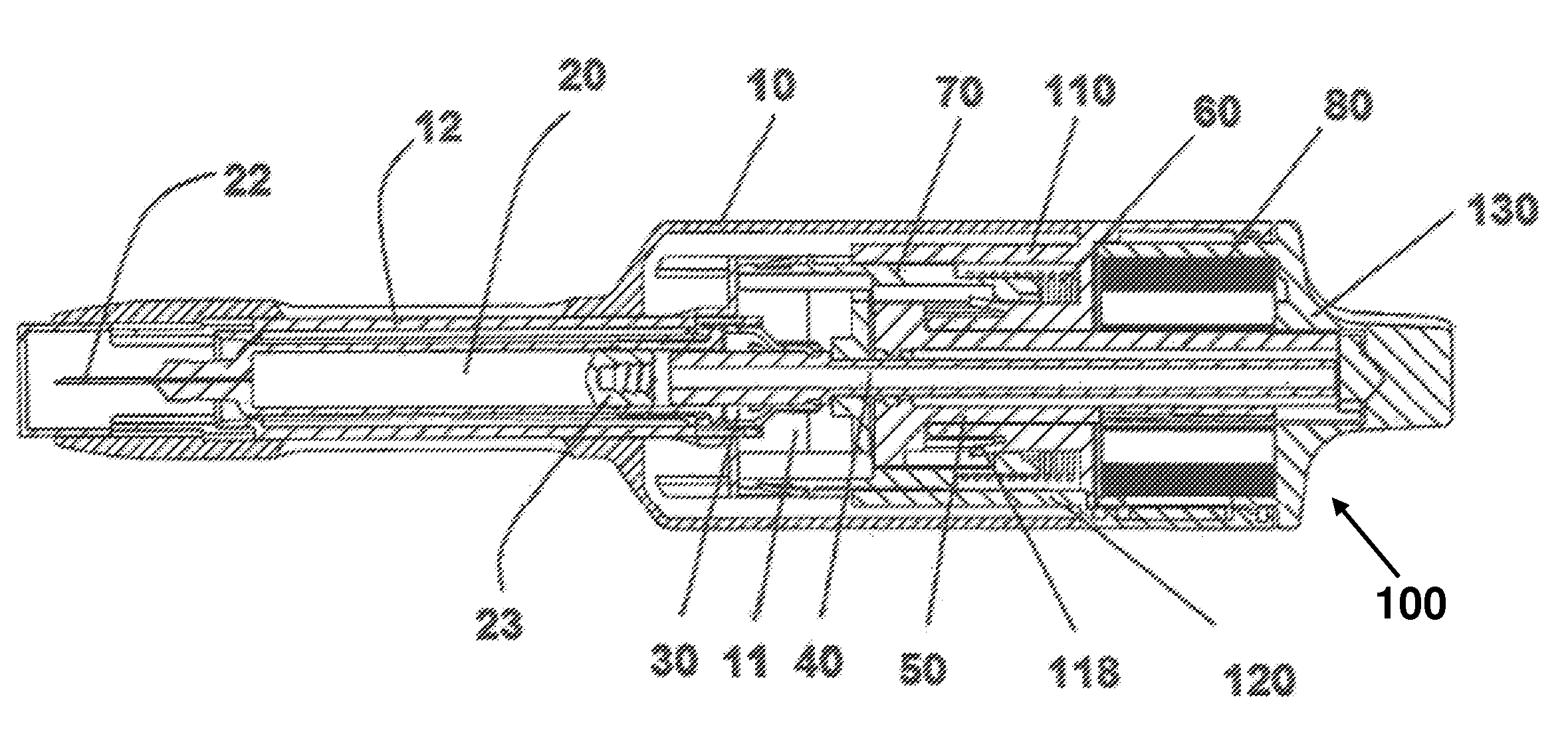
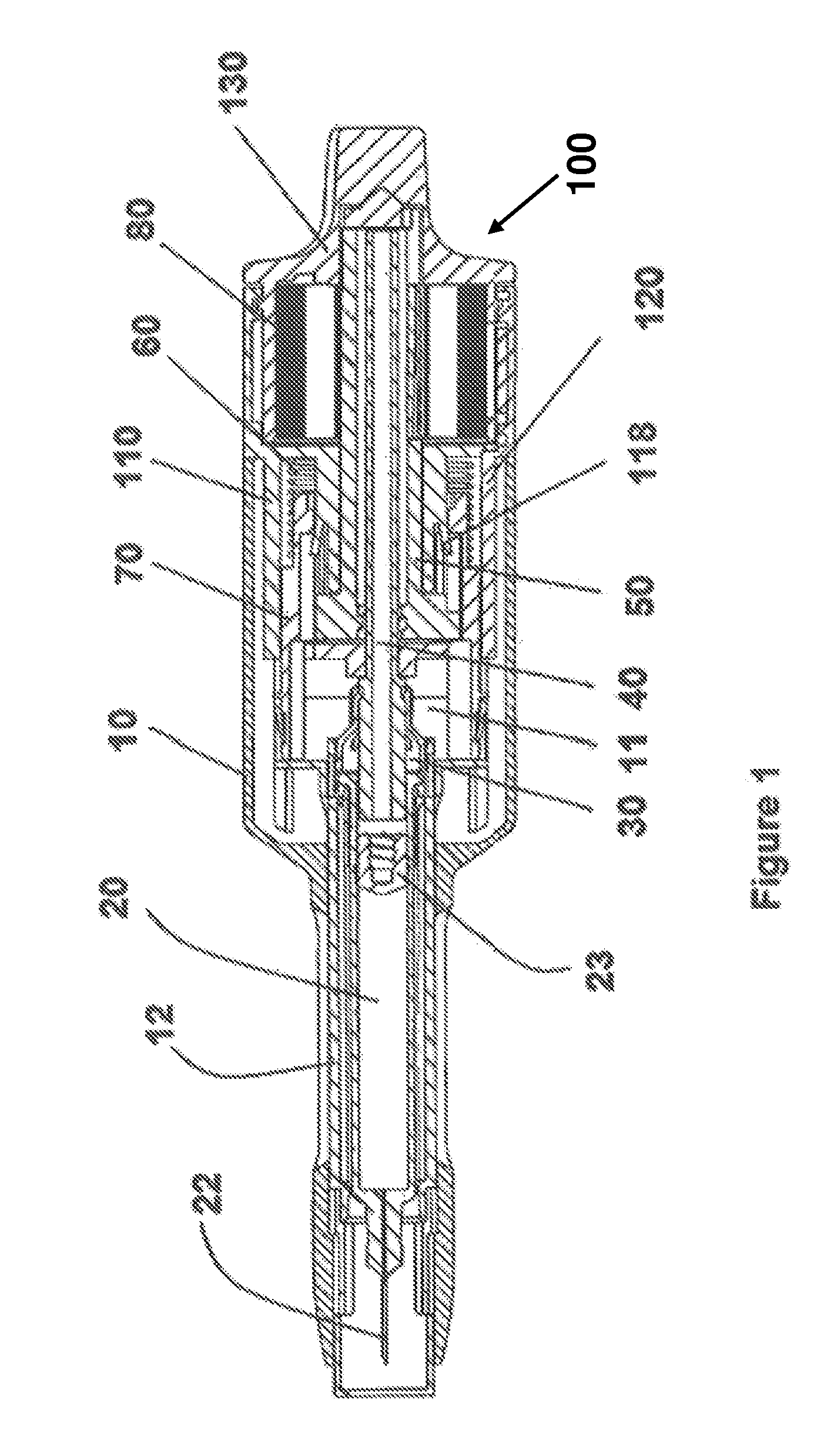
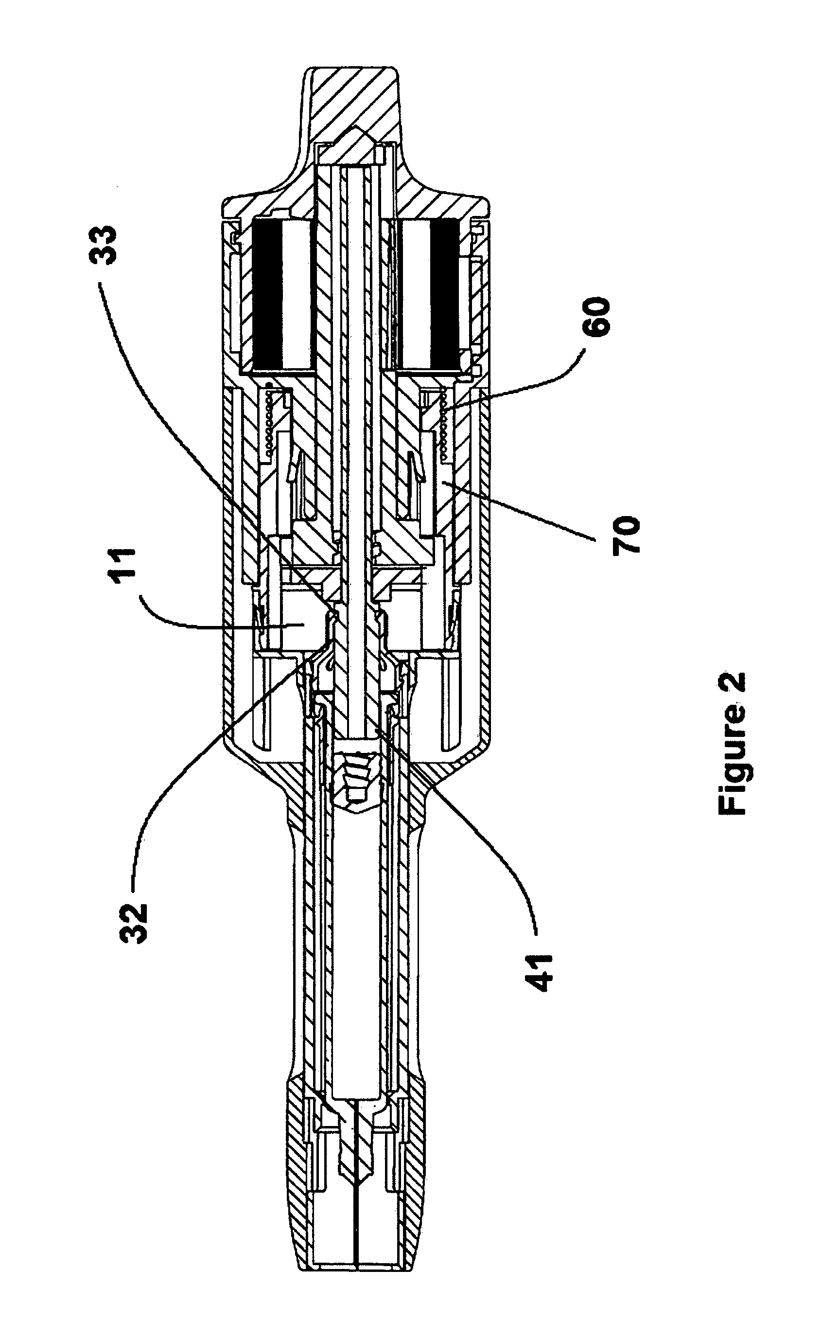
[0029]The embodiment of the injector shown in the drawings comprises a housing having a proximal housing 10 and a distal housing 100, an elongated needle shield sleeve 11, a container driver 30, a plunger rod 40, a plunger rod driving member 50, a helical spring 60, an actuating sleeve 70 and an energy accumulating member 80. The proximal housing 10 being an elongated tube-shaped comprising of two sections: a proximal section and a distal se...


PUM


Abstract

The present invention relates to an injection device comprising a housing (10, 100), a container holder (12) arranged within said housing having a container (20) adapted to contain medicament to be delivered through a needle, plunger drive means (40), an energy accumulating member (80) adapted to accumulate and transfer energy to said plunger drive means wherein said device further comprises container driver means (30) arranged and designed to be connected to the plunger drive means and to the container holder for holding the container and its needle stationary within said housing before said energy is provided to the drive means and for urging the container towards the proximal end of the device when said energy is provided to the drive means whereby a needle penetration and respectively an injection are performed.

Description

TECHNICAL FIELD[0001]The present invention relates to an injection device having several automatic functions such as automatic penetration, automatic injection and automatic safety means for preventing from accidental needle sticks and in particular an injection device capable of handling medicament in fluid form having high viscosity.BACKGROUND ART[0002]The present invention relates to injection devices for injecting medicament in fluid form having high viscosity which means that these devices require high forces in order to press the fluid through a needle when injecting the medicament.[0003]Auto-injectors, or pen-injectors have been on the market for many years. One of the first auto-injectors was developed for war-times, which was activated by pressing the injector against a body part for activating it. The main concern was to have the medicament injected as fast as possible, without much concern for the patient or for handling safety aspects. During the recent years some medica...

Claims


Application Information

Patent Timeline
Patent Type & Authority Patents(United States)
IPC IPC(8): A61M5/20
CPCA61M5/2033A61M5/326A61M2005/3247A61M2005/206A61M2005/2013A61M5/31583
Inventor KRONESTEDT, VICTOR
Owner SHL MEDICAL AG
Learn More