
Button cannula

a cannula and button technology, applied in the field of cannulas, can solve the problem that the inner flange of such cannulas is generally not wide enough to provide the optimum amount of stability, and achieve the effect of improving stability

Active Publication Date: 2011-10-18
ARTHREX
View PDF12 Cites 129 Cited by
  • Summary
  • Abstract
  • Description
  • Claims
  • Application Information

AI Technical Summary

Benefits of technology

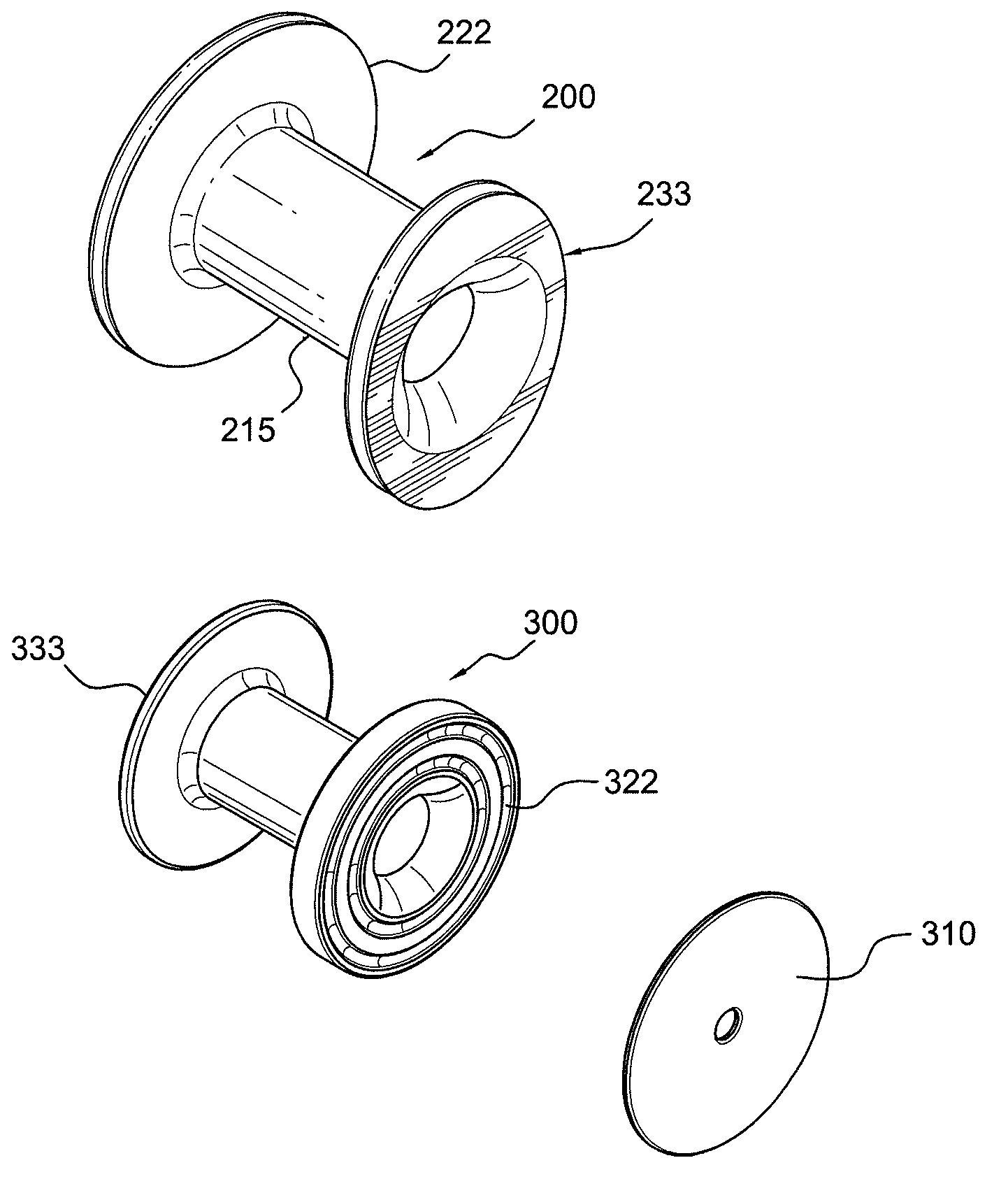
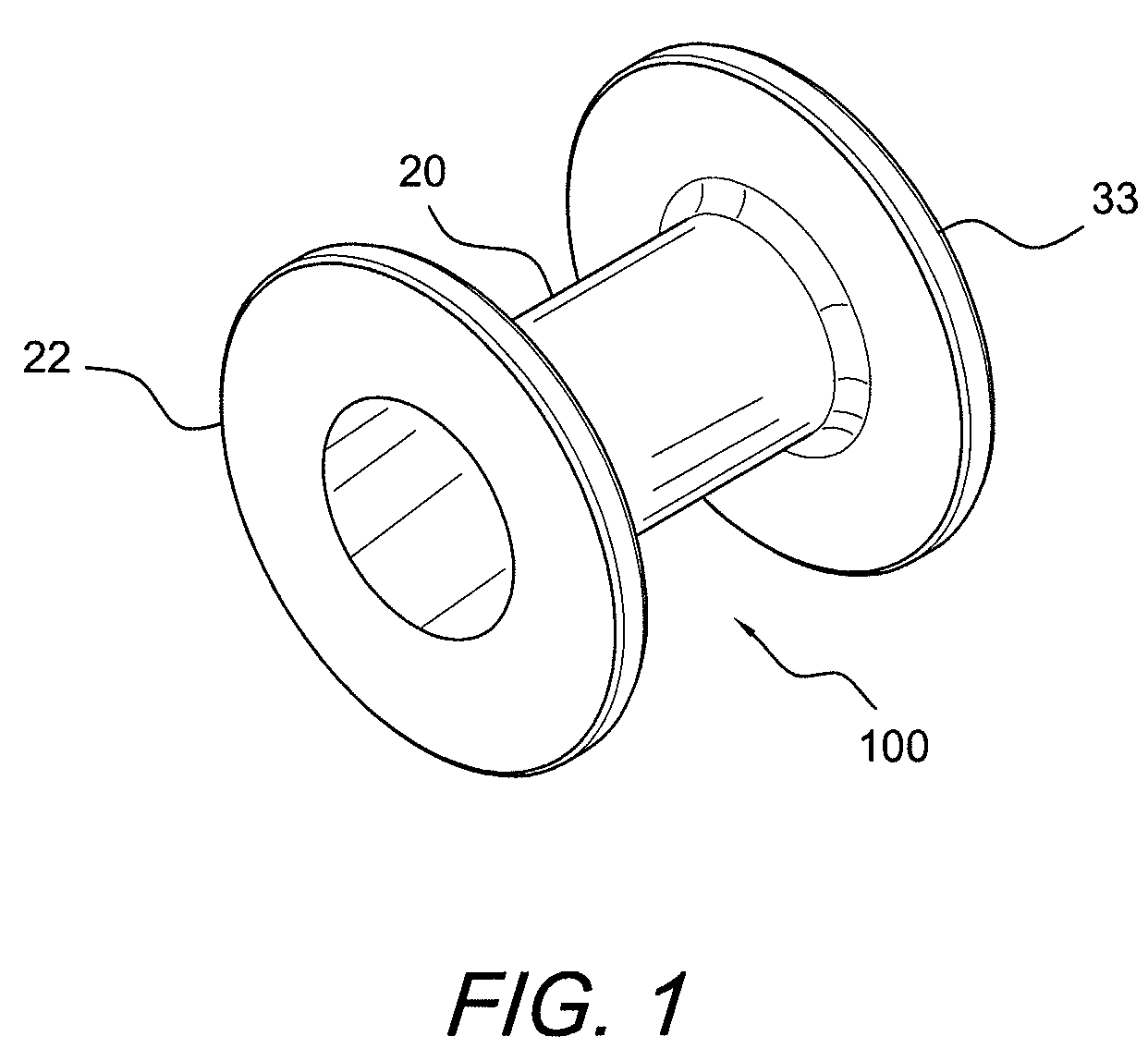
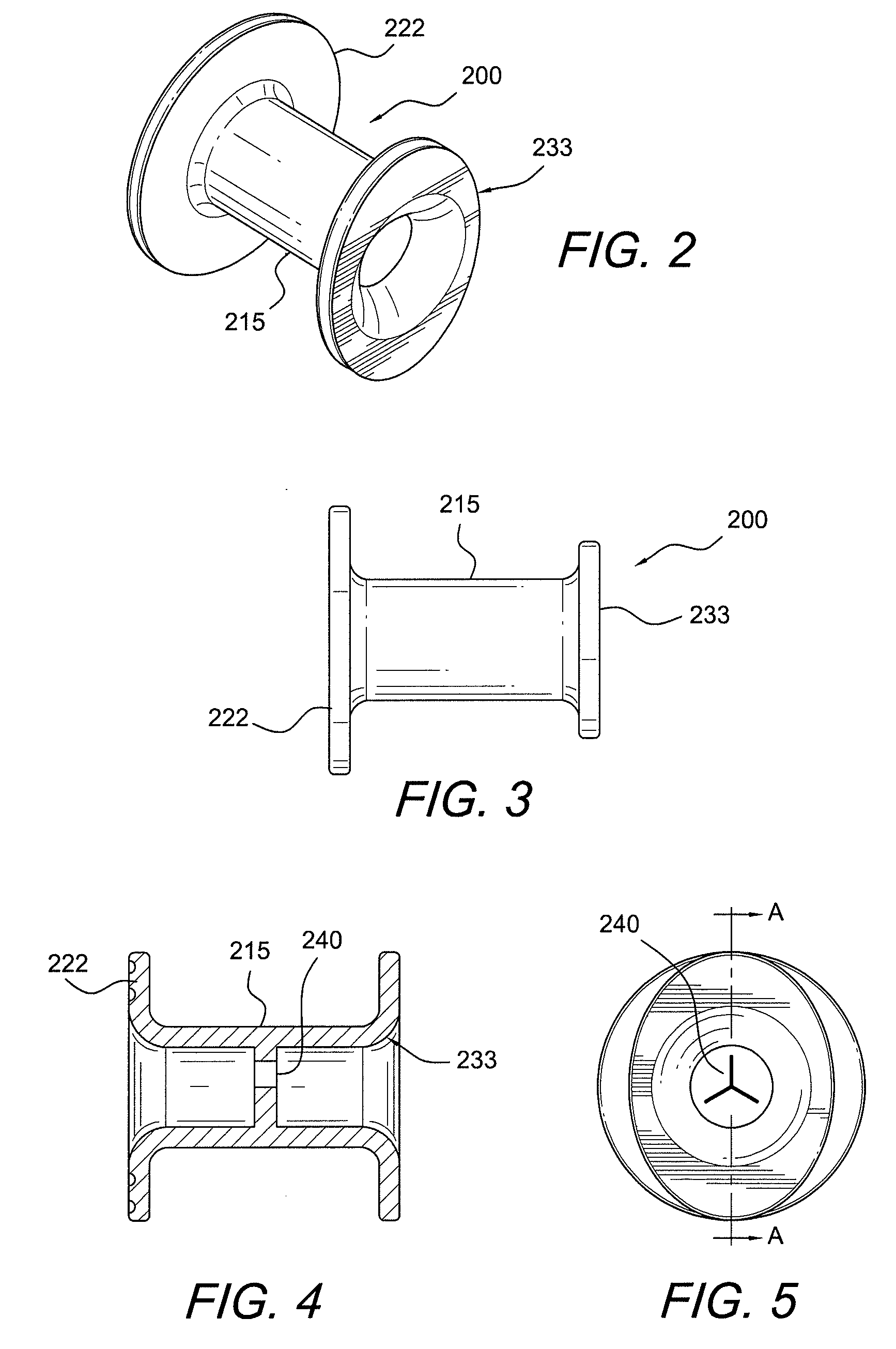
[0007]The present invention provides a flexible button cannula for arthroscopic surgery made from silicone, or a similar flexible material. Exemplary embodiments of the button cannula have large inner and outer flanges for improved stability when installed into the body. Further, exemplary embodiments of the button cannula include two fluid dams. A first dam is located within the cannula elongated portal between the inner and outer flanges and prevents fluid from squirting out of the body when instruments are being inserted through the cannula. A second dam is located at the outer, or top, flange (i.e., the flange that remains outside of the body) to prevent fluid from squirting when the cannula itself is being inserted within the body. Exemplary embodiments of the button cannula also include an outer, or top, flange that is thicker than the inner, or bottom, flange, to prevent the over insertion of the cannula into the body.

Problems solved by technology

Prior art cannulas are also generally rigid and inflexible, and since the portals through which endoscopic surgery is performed are desired to be as small in diameter as possible, the inner flanges of such cannulas are generally not wide enough to provide the optimum amount of stability while instruments are being transferred therethrough.

Method used


Image

  • Button cannula
  • Button cannula
  • Button cannula

Examples


Embodiment Construction

[0019]In the following detailed description, reference is made to various specific embodiments in which the invention may be practiced. These embodiments are described with sufficient detail to enable those skilled in the art to practice the invention, and it is to be understood that other embodiments may be employed, and that structural and logical changes may be made without departing from the spirit or scope of the present invention.

[0020]The present invention is a flexible button cannula for arthroscopic surgery made from silicone, or a similar flexible material. Exemplary embodiments of the button cannula have large inner and outer flanges for improved stability when installed into the body. Further, exemplary embodiments of the button cannula include two fluid dams. A first dam is located within the cannula elongated portal between the inner and outer flanges and prevents fluid from squirting out of the body when instruments are being inserted through the cannula. A second dam...


PUM


Abstract

Flexible button cannulas for arthroscopic surgery made from silicone, or a similar flexible material. Exemplary embodiments of the button cannula have large inner and outer flanges for improved stability when installed into the body. Exemplary embodiments of the button cannula include two fluid dams. A first dam is located within the cannula elongated portal between the inner and outer flanges and prevents fluid from squirting out of the body when instruments are being inserted through the cannula. A second dam is located at the outer, or top, flange (i.e., the flange that remains outside of the body) to prevent fluid from squirting when the cannula itself is being inserted within the body. Exemplary embodiments of the button cannula also include an outer, or top, flange that is thicker than the inner, or bottom, flange, to prevent the over insertion of the cannula into the body.

Description

CROSS-REFERENCE TO RELATED APPLICATIONS[0001]This application claims the benefit of U.S. Provisional Application No. 61 / 032,872, filed Feb. 29, 2008, and of U.S. Provisional Application No. 61 / 111,214, filed Nov. 4, 2008, the entire disclosures of which are incorporated by reference herein.FIELD OF THE INVENTION[0002]The present invention relates to cannulas having inner and outer flanges separating a portal for allowing various surgical instruments to be introduced in the body.BACKGROUND OF THE INVENTION[0003]Cannulas are generally used in endoscopic surgical procedures which enable closed surgery to be performed via portals. A variety of elongated instruments may be passed through the portals to gain access to an internal surgical work site (e.g., a knee, a shoulder, etc). Very often a disposable cannula is inserted into the portal in order to provide a convenient passageway through which various instruments may pass.[0004]Because many arthroscopic procedures require the use of pr...

Claims


Application Information

Patent Timeline
Patent Type & Authority Patents(United States)
IPC IPC(8): A61M5/178
CPCA61B17/3423A61B17/3431A61B17/3498A61B2017/3419A61B2017/3425A61B2017/3441A61B2017/3482
Inventor MORRISON, DAVID S.DREYFUSS, PETER J.DOONEY, JR., THOMAS
Owner ARTHREX
Learn More