Double-clutch transmission

a transmission and double-clutch technology, applied in mechanical equipment, transportation and packaging, gearing, etc., can solve the problems of unsatisfactory, unfavorable installation space, and automobile in a failed state, and achieve the effect of reducing the vehicle cos

Inactive Publication Date: 2011-10-25
MITSUBISHI MOTORS CORP +1
View PDF7 Cites 18 Cited by
  • Summary
  • Abstract
  • Description
  • Claims
  • Application Information

AI Technical Summary

Benefits of technology

It is an object of the present invention to provide a double-clutch transmission that can reduce the vehicle cost.

Problems solved by technology

On the other hand, when the information on the engine rotational speed is not conveyed to the double-clutch transmission because, for example, the sensor that measures the rotational speed on the engine side fails, the automobile enters a failed state.
When the number of sensors increases, consideration must be given to cost increase and installation space, which is not desirable.

Method used


Image

  • Double-clutch transmission
  • Double-clutch transmission
  • Double-clutch transmission

Examples


Embodiment Construction

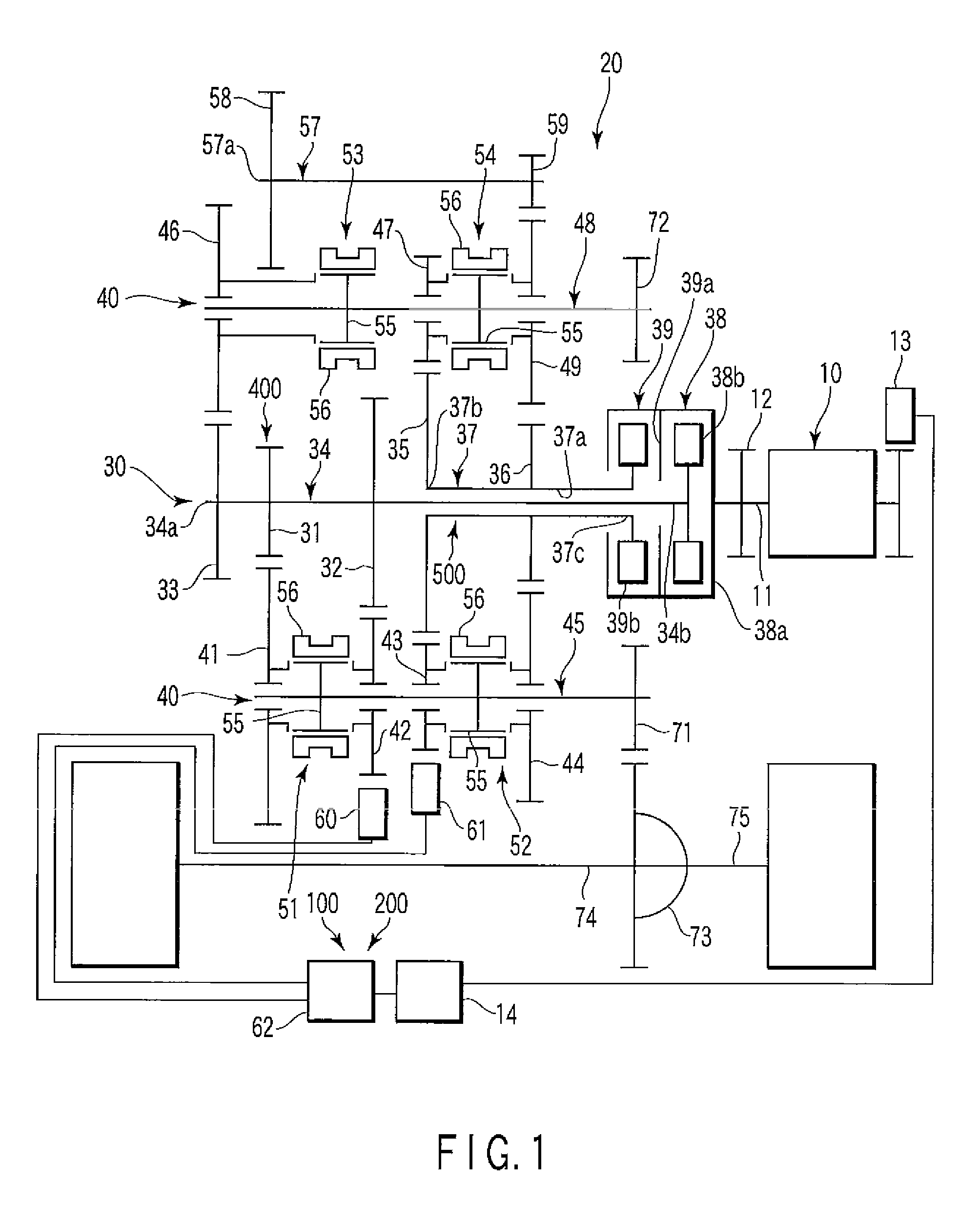
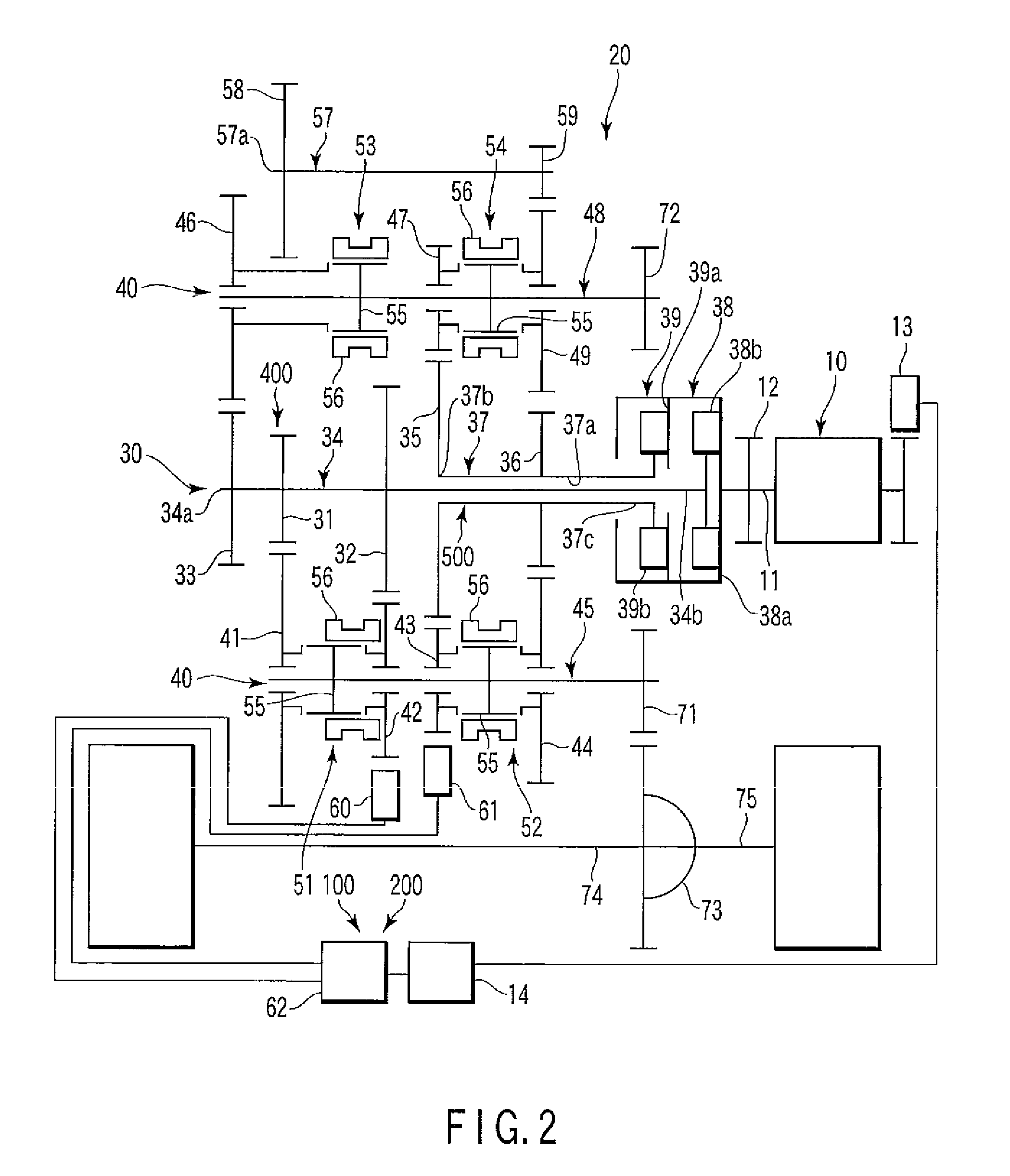
Referring now to FIGS. 1 to 3, a double-clutch transmission 20 according to one embodiment of the present invention will be described. FIG. 1 is a schematic block diagram of the double-clutch transmission 20. As shown in FIG. 1, the double-clutch transmission 20 is connected to an engine 10, and rotation of the engine 10, that is, motive power, is conveyed to the double-clutch transmission 20.

A flywheel 12 is mounted to an output shaft 11 of the engine 10. In addition, a crank angle sensor 13 which measures the engine rotational speed is installed to the engine 10. The crank angle sensor 13 is connected to an engine ECU (Electronic Control Unit) 14. The rotational speed information of the engine 10 measured by the crank angle sensor 13 is conveyed to the engine ECU 14. Note that the engine 10 and the double-clutch transmission 20 are mounted on, for example, an automobile (not illustrated).

The double-clutch transmission 20 is provided with an input system 30, an output system 40, a ...


PUM


Abstract

In a double-clutch transmission, a clutch of an input shaft which is not synchronously rotated with a output shaft is connected to synchronize the speed of rotation of the input shaft with that of the engine, and the rotational speed of the input shaft is measured to thereby detect a engine rotational speed.

Description

CROSS-REFERENCE TO RELATED APPLICATIONSThis application is based upon and claims the benefit of priority from prior Japanese Patent Application No. 2007-080256, filed Mar. 26, 2007, the entire contents of which are incorporated herein by reference.BACKGROUND OF THE INVENTION1. Field of the InventionThe present Invention relates to a double-clutch transmission which enables continuous shift transmission by a synchromesh mechanism with interruption of power transmission suppressed to a minimum by use of two clutches and two input shafts.2. Description of the Related ArtAs an automatic transmission of a vehicle, there is a double-clutch transmission. For the double-clutch transmission, for example, a constantly meshing gear mechanism in which a drive gear and a driven gear constantly engage with each other is used, which suppresses loss of power transmission during shift transmission.For the structure of this double-clutch transmission, a structure that combines an input system using t...

Claims


Application Information

Patent Timeline
Patent Type & Authority Patents(United States)
IPC IPC(8): F16H3/08F16H3/093F16H59/40F16H59/42F16H59/46F16H61/02F16H61/68F16H61/682
CPCF16H61/12F16H61/688F16H3/006F16H59/42F16H2003/0931F16H2061/122Y10T74/19242F16H2306/48F16H2061/1284Y10T74/19288Y10T74/1926Y10T74/19228F16H2200/0052
Inventor MATSUSHITA, MASAHIROKOMORI, KATSUHIROKIMURA, TAKAO
Owner MITSUBISHI MOTORS CORP
Why Eureka
Try Eureka