
Image pickup device adaptable to display fewer vertical pixels

a pickup device and vertical pixel technology, applied in the direction of picture signal generators, television system scanning details, television systems, etc., can solve the problems of increasing production costs, complicated circuit configuration, and difficult to determine image configuration

Inactive Publication Date: 2011-10-25
CANON KK
View PDF8 Cites 0 Cited by
  • Summary
  • Abstract
  • Description
  • Claims
  • Application Information

AI Technical Summary

Benefits of technology

The present invention provides an image pickup device that can read the signal charges from the pixels of a predetermined number of rows in the image pickup element, even if the number of pixels in the vertical direction is less than the number of pixels in the single image pickup operation. This allows for a thinner image display unit and simplifies the circuit configuration and reduces the size of the circuitry. The device also includes a color filter array with filters of different colors arranged in the horizontal and vertical directions, and can form a color image even in a dark situation. The device can also add the signal charges of predetermined pixels in the vertical direction to create an image signal. The color filters are arranged in rows, and the method of adding the signal charges can involve adding the signals of adjacent rows or adding the signals of pixels in the same column. The device can use a combination of cyan, green, yellow, and magenta filters or a combination of yellow, magenta, and green filters.

Problems solved by technology

However, in such conventional image pickup device, if the image pickup element is combined with an image display unit of which the number of pixels in the vertical direction is less than that outputted from the image pickup element in a single image taking operation, the image pickup element is always required to output the image signal of all the pixels that can be in a single image taking operation, so that there is not only required a long time for each image taking operation but, in case of displaying the images in succession for image recording into and reading from the image memory the renewal of the image takes a long time so that it becomes difficult to determine the image configuration.
Also, since the number of pixels in the vertical direction is different between the image pickup element and the image display unit, there are required an image memory and vertical thinning-out means for achieving the synchronization with the image display unit, whereby the circuit configuration becomes complicated and the production cost increases significantly.

Method used


Image

  • Image pickup device adaptable to display fewer vertical pixels
  • Image pickup device adaptable to display fewer vertical pixels
  • Image pickup device adaptable to display fewer vertical pixels

Examples


first embodiment

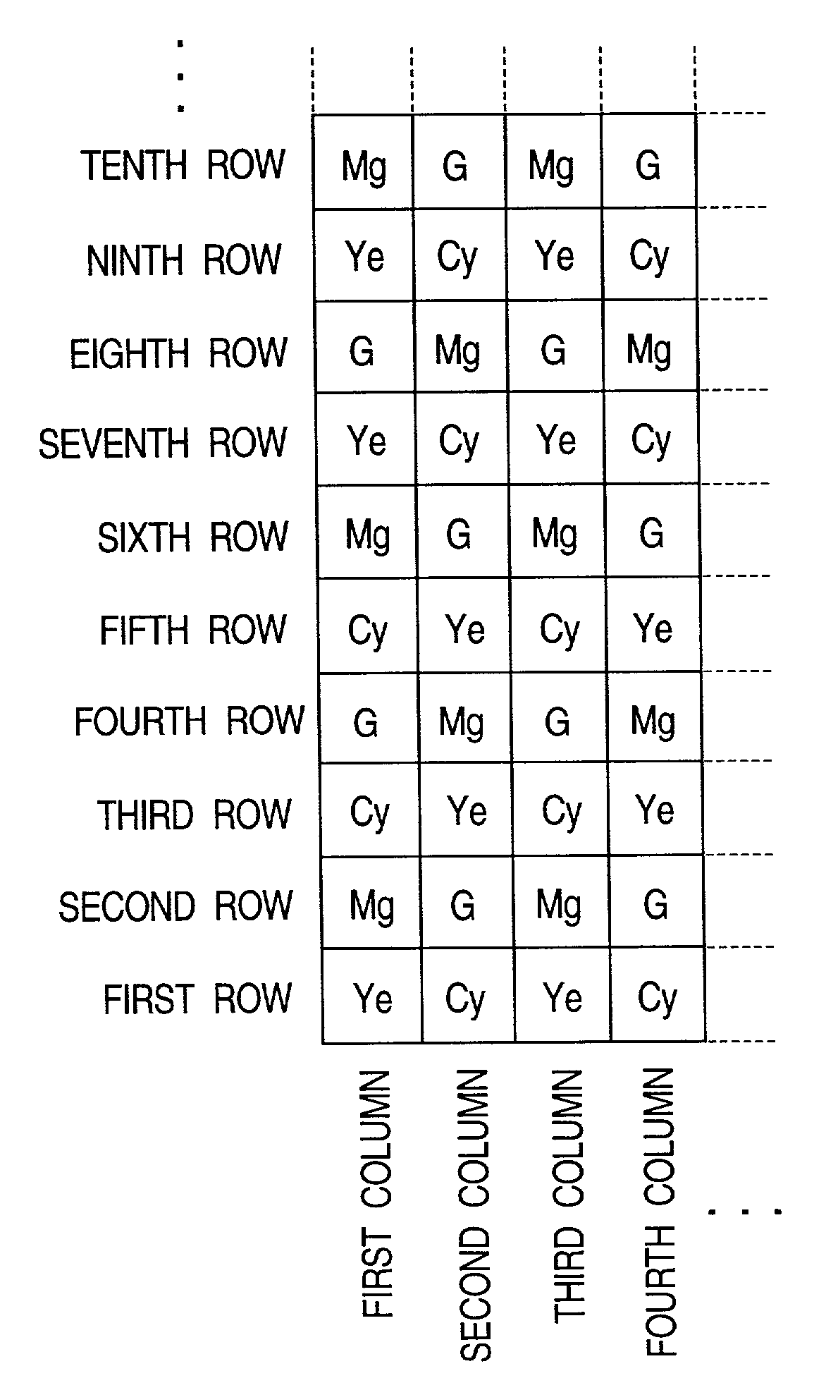
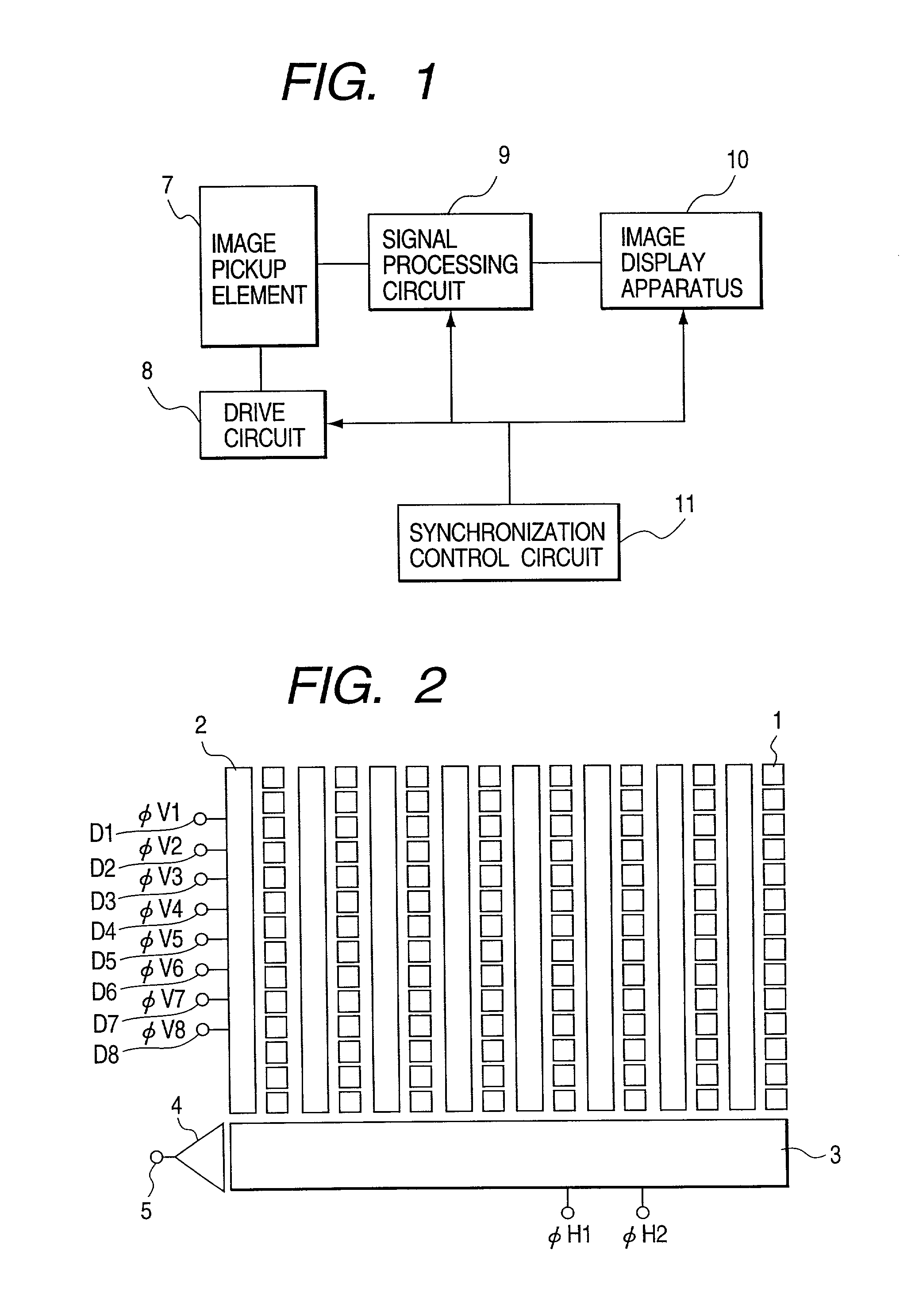
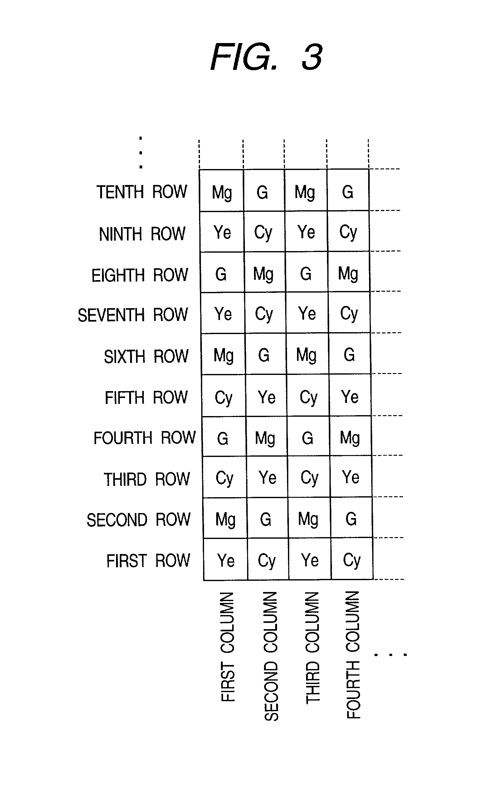
[0034]At first there will be explained a first embodiment, in which the image pickup device is composed, as shown in FIG. 1, of a color filter array of color filters arranged in the horizontal and vertical directions, an unrepresented lens, an image pickup element 7 composed of an interline CCD image sensor, a drive circuit 8 therefor, a signal process circuit 9 for applying necessary processes to the image signal from the image pickup element 7, an image display unit 10 composed for example of an electronic view finder or a liquid crystal display for displaying an image constructed from the image signal, and a synchronization control circuit 11 for controlling the entire image pickup device. The image display unit 10 has a number of pixels in the vertical direction, smaller than the number of pixels that can be outputted from the image pickup element 7 in a single image pickup operation.

[0035]The image pickup element 7 is composed, as shown in FIG. 2, of photoelectric converting el...

second embodiment

[0057]In the following there will be explained, with reference to FIGS. 14 to 25, the method of reading the signal charges accumulated in the pixels 1 respectively corresponding to the color filters and outputting the corresponding image signal. The present second embodiment is capable of thinning-out the signal charges from the pixels 1 of predetermined rows, thereby outputting the charges of a row in every 4 rows in the vertical directions as the image signal.

[0058]The read-out operation is started from a state in which signal charges respectively corresponding to the color filters are accumulated in the pixels 1, as shown in FIG. 14.

[0059]At first, within the VCCD 2, the electrodes D1, D3, D5 and D7 are respectively given the read-out drive pulses φV1, φ3, φ5 and φV7 as shown in FIG. 15 to read the signal charges of the pixels 1. From this point, the pixels 1 initiate the accumulation of the signal charges by photoelectric conversion, but such signal charge accumulation is not il...


PUM


Abstract

In an image pickup device, in order to enable signal charge read-out from the image pickup element in a thinning-out manner from the pixels of predetermined rows, even in case the image display unit has a number of pixels in the vertical direction smaller than the number of pixels that can be outputted from the image pickup element in a single image pickup operation, and also to form a color image even from the thinned-out image signal from the image pickup element, the signal charges are read in thinning-out manner from the pixels of predetermined rows, then there is formed a line-sequential color difference signal consisting of a signal S(odd) in which color signals (Ye+Mg) and (Cy+G) are repeated in this order and a signal S(even) in which color signals (Ye+G) and (Cy+Mg) are repeated in this order and an image signal corresponding to a row in every four rows in the vertical direction is outputted from the image pickup element.

Description

BACKGROUND OF THE INVENTION[0001]1. Field of the Invention[0002]The present invention relates to an image pickup device equipped with an image pickup element such as a CCD (charge coupled device) of an interline structure with a function of reading all the pixels.[0003]2. Related Background Art[0004]The image pickup device of a large pixel number, suitable for use in an electronic still camera of a high resolution or the like, is generally represented by a CCD image sensor of interline structure. Such CCD image sensor is provided, as shown in FIG. 37, with photoelectric converting elements (pixels) 101 arranged in a matrix and adapted to convert the incident light into electric charges; vertical charge transfer units (VCCD) 102 for reading the charges accumulated in such pixels 101 and transferring the charges in the vertical direction; a horizontal charge transfer unit (HCCD) 103 for transferring the signal charges, transferred from the VCCD's 102, in the horizontal direction; and ...

Claims


Application Information

Patent Timeline
Patent Type & Authority Patents(United States)
IPC IPC(8): H04N3/14H04N23/12
CPCH04N9/045H04N23/633H04N25/70H04N25/136
Inventor YANAI, TOSHIKAZUSAKAEGI, YUJI
Owner CANON KK
Learn More