Motion control system for vehicle

a technology of motion control and vehicle, which is applied in the direction of process and machine control, instruments, cycle equipment, etc., can solve the problems of deteriorating the ride feeling of an occupant(s) of the vehicle, vehicle front-to-back, and vehicle body as a vertical force, so as to reduce the anti-pitching effect and reduce the pitch angl

a technology of motion control and vehicle, which is applied in the direction of process and machine control, instruments, cycle equipment, etc., can solve the problems of deteriorating the ride feeling of an occupant(s) of the vehicle, vehicle front-to-back, and vehicle body as a vertical force, so as to reduce the anti-pitching effect and reduce the pitch angl

US8046130B2Inactive Publication Date: 2011-10-25ADVICS CO LTD

Image

  • Motion control system for vehicle
  • Motion control system for vehicle
  • Motion control system for vehicle

Examples


Embodiment Construction

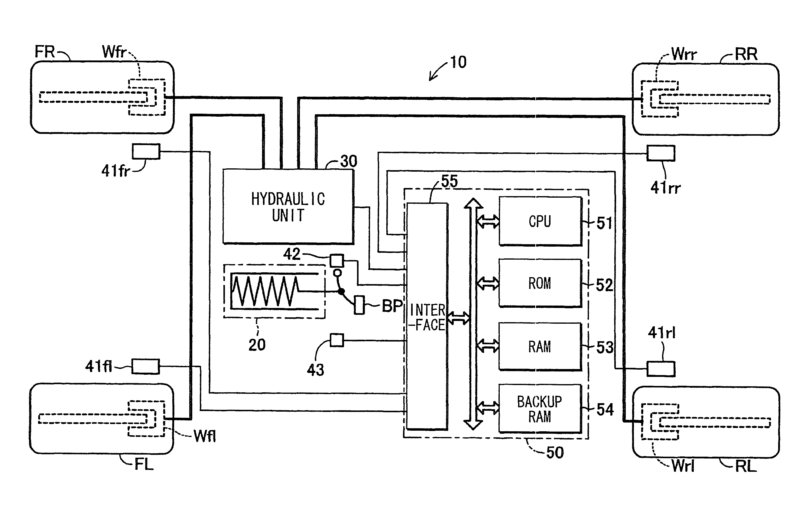
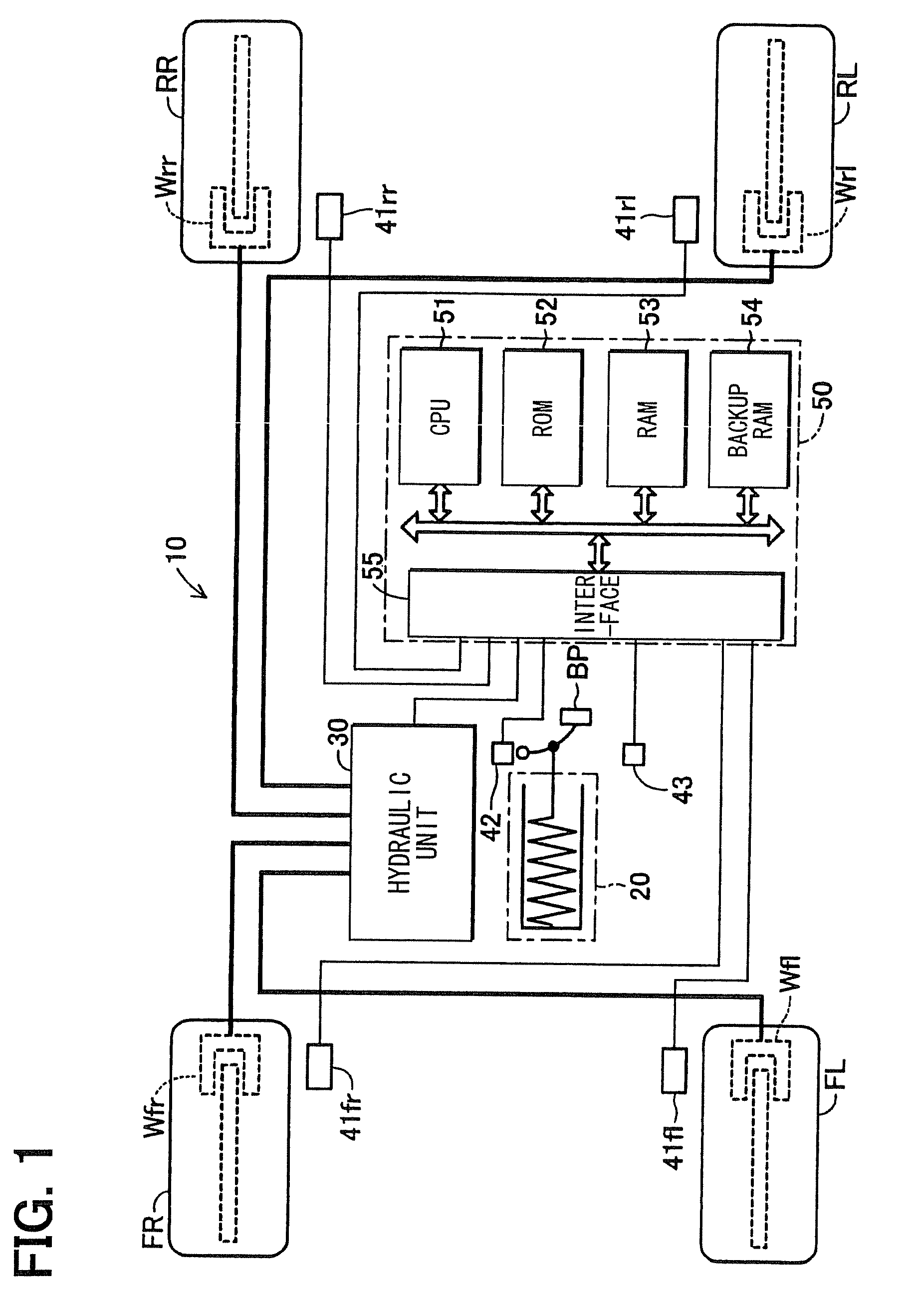
[0043]A vehicle motion control system according to an embodiment of the present invention will be described with reference to the accompanying drawings. FIG. 1 shows a schematic structure of a vehicle, in which the vehicle motion control system 10 of the present embodiment is installed.

[0044]In the vehicle motion control system 10, a brake-by-wire system is provided, and a brake pedal BP (a brake operating member) and a brake fluid pressure circuit are separated. The vehicle motion control system 10 includes a stroke simulator mechanism 20 and a hydraulic unit 30. The hydraulic unit 30 applies a brake fluid hydraulic pressure to generate a brake force at respective vehicle wheels FL, FR, RL, RR.

[0045]The stroke simulator mechanism 20 includes a known reaction force applying mechanism, which applies an appropriate reaction force (=brake pedal pressing force Fp) that corresponds to a stroke of the brake pedal BP, to the brake pedal BP. The reaction force applying mechanism will not be...


PUM


Abstract

A motion control system is applied to a vehicle, which has front wheel side suspensions with an anti-dive geometry and rear wheel side suspensions with an anti-lift geometry. A degree of an anti-lift effect of the anti-lift geometry is larger than a degree of an anti-dive effect of the anti-dive geometry. Normally, a controller controls a hydraulic unit such that a brake force distribution between front wheels and rear wheels during a braking-period is adjusted to a basic distribution. In contrast, in a state where abrupt application of brakes is started, the controller controls the hydraulic unit such that the brake force distribution is adjusted to a first distribution, at which a brake force respectively applied to the rear wheels is larger than that of the basic distribution only for a predetermined short time period upon starting of the application of the brakes.

Description

CROSS REFERENCE TO RELATED APPLICATION[0001]This application is based on and incorporates herein by reference Japanese Patent Application No. 2007-040623 filed on Feb. 21, 2007.TECHNICAL FIELD[0002]The present invention relates to a motion control system for a vehicle.BACKGROUND ART[0003]Front wheel side suspensions, which have an anti-dive geometry, and rear wheel side suspensions, which have an anti-lift geometry, are well known in the art to limit pitching of the vehicle, which occurs during a braking period of applying brakes. With such front and rear wheel side suspensions, an anti-dive effect, which limits diving of a vehicle body (a phenomenon of sinking of a front side of the vehicle body) during the braking period, and an anti-lift effect, which limits lifting of the vehicle body (a phenomenon of floating of a rear side of the vehicle body) during the braking period, are implemented, so that the pitching is limited. Hereinafter, the terms ā€œanti-diveā€ and ā€œanti-liftā€ may als...

Claims


Application Information

Patent Timeline
25 Oct 2011
Publication
US8046130B2
IPC
B60T8/1755
CPC
B60T8/1755; B60T8/1766; B60T2260/06
Inventors
TAKAHARA, YASUO; ARAKAWA, HARUO