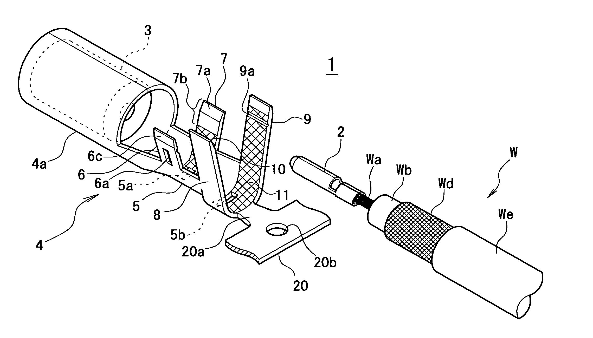
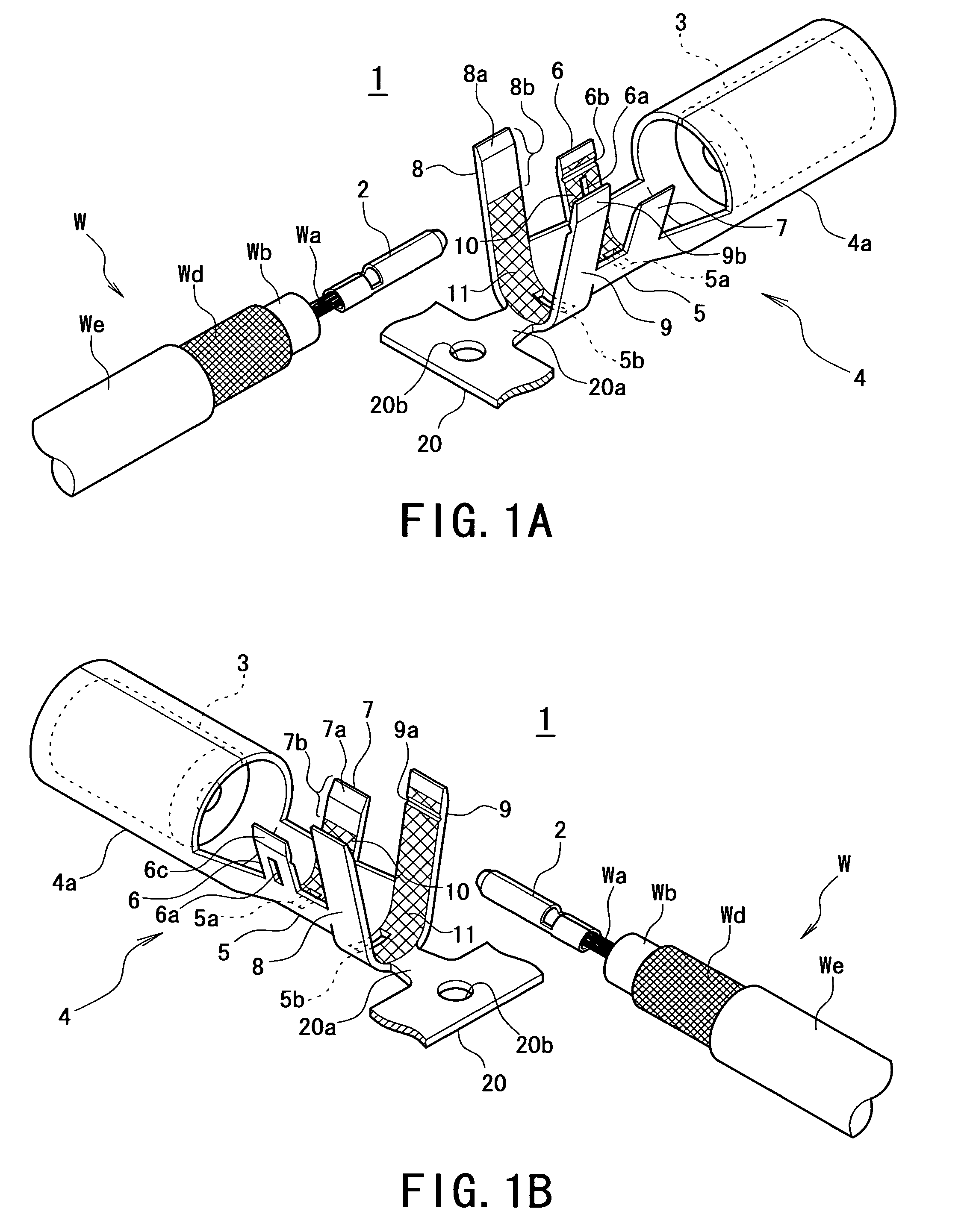
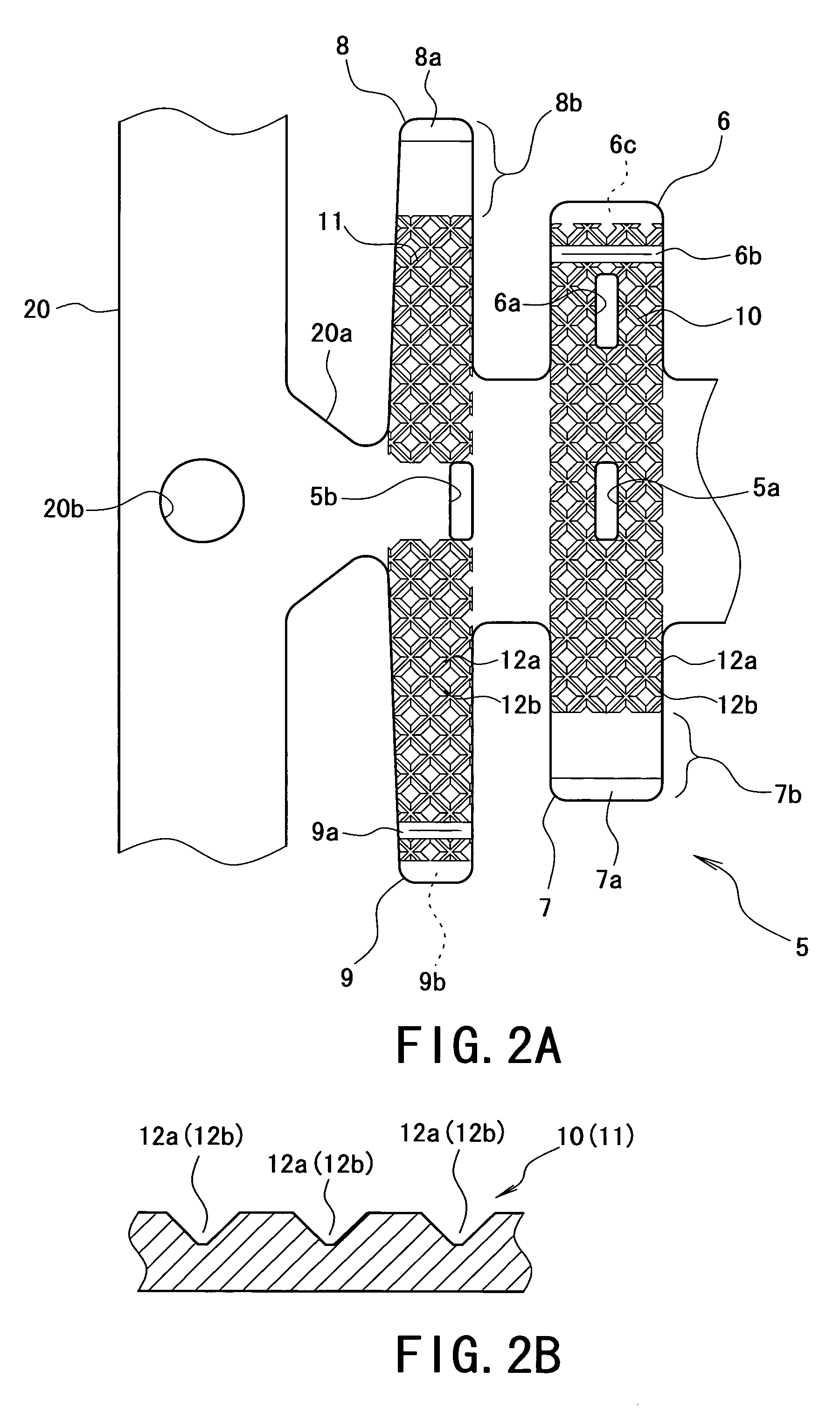
[0013]The outer conductor terminal has the configuration in which the first and second shielded conductor crimping portions are provided to be crimped onto the shielded conductor which is exposed by stripping the sheath at the end of the shielded cable, the shielded conductor crimping portions are crimped such that the second shielded conductor crimping portion overlaps the first shielded conductor crimping portion, reticulated knurling grooves formed on the inner surfaces of the first and second shielded conductor crimping portions, the reticulated knurling grooves are not formed on an overlapping portion of the inner surface of the second shielded conductor crimping portion which is placed on the first shielded conductor crimping portion. The area on which the reticulated knurling grooves are formed is thus decreased as compared with that in a case where the reticulated knurling grooves are formed on the entire inner surfaces of the shielded conductor crimping portions as with a conventional art. Accordingly, it is possible to suppress an increase in the cost of a die used in press work to form the reticulated knurling grooves on the shielded conductor crimping portions, and to decrease pressing pressure in the press work, thereby producing favorable effects such as better uniformity in the shape of reticulated knurling grooves, which result in improved productivity. In addition, occurrence of a burr can be suppressed in portions such as the tips of the shielded conductor crimping portions, thereby preventing the shielded conductor from being damaged.
[0014]Owing to the configuration in which the outer conductor terminal comprises the tapered surface formed on the outer surface at the tip of the first shielded conductor crimping portion, a tapered surface formed on the inner surface at the tip of the second shielded conductor crimping portion, which can slide on the tapered surface of the outer surface of the first shielded conductor crimping portion, wherein the reticulated knurling grooves are not formed on the portion of the inner surface of the first shielded conductor crimping portion which corresponds to the tapered surface of the outer surface of the first shielded conductor crimping portion, the area of the reticulated knurling grooves is further decreased by the area of the tapered surface. By not forming the reticulated knurling grooves on the portion corresponding to the tapered surface, when the tapered surfaces at the tips of the shielded conductor crimping portions come into contact with each other, they can smoothly slide without being caught. Accordingly, productivity in the crimping process can be improved.
[0015]In addition, owing to the configuration in which the outer conductor terminal further comprises the first and second sheath crimping portions to be crimped onto the sheath, wherein the first and second sheath crimping portions are crimped such that the second sheath crimping portion overlaps the first sheath crimping portion, and reticulated knurling grooves formed on the inner surfaces of the first and second sheath crimping portions, wherein the reticulated knurling grooves are not formed on the overlapping portion of the inner surface of the second sheath crimping portion which is placed on the first sheath crimping portion, the area on which the reticulated knurling grooves are formed is decreased as compared with that in a case where the reticulated knurling grooves are formed on the entire inner surfaces of the sheath crimping portions as with a conventional art. Accordingly, it is possible to suppress an increase in the cost of a die used in press work to form the reticulated knurling grooves on the sheath crimping portions, and to decrease pressing pressure in the press work, thereby producing favorable effects such as better uniformity in the shape of the reticulated knurling grooves, which result in improved productivity. In addition, occurrence of a burr can be suppressed in portions such as the tips of the sheath crimping portions, thereby preventing the sheath from being damaged.
[0016]Further, owing to the configuration in which the outer conductor terminal further comprises a tapered surface formed on the outer surface at the tip of the first sheath crimping portion, and a tapered surface formed on the inner surface at the tip of the second sheath crimping portion, which can slide on the tapered surface of the first sheath crimping portion, wherein the reticulated knurling grooves are not formed on the portion of the inner surface of the first sheath crimping portion which corresponds to the tapered surface of the outer surface of the first sheath crimping portion, the area of the reticulated knurling grooves is further decreased by the area of tapered surface. By not forming the reticulated knurling grooves on the portion which corresponds to the tapered surface, when the tapered surfaces on the tips of the sheath crimping portions come into contact with each other, they can smoothly slide without being caught. Accordingly, productivity in the crimping process can be improved.


