Driving force generation system, vehicle using the system, and method for controlling the system

a technology of driving force and system, applied in the direction of motor/generator/converter stopper, electric generator control, electric devices, etc., can solve the problems of reducing drivability (driving characteristic) and excessive degradation in each power storage uni

Active Publication Date: 2011-11-08
TOYOTA JIDOSHA KK
View PDF11 Cites 43 Cited by
  • Summary
  • Abstract
  • Description
  • Claims
  • Application Information

AI Technical Summary

Benefits of technology

[0022]By the present invention, a driving force generation system enabling power management of the system as a whole, a vehicle provided with the system, and a method of controlling the same can be provided.

Problems solved by technology

Therefore, if a target value of driving force is set exceeding the allowable range of power supply or power regeneration of the plurality of power storage units as a whole, excessive degradation possibly occurs in each of the power storage units, or drivability (driving characteristic) possibly lowers.

Method used


Image

  • Driving force generation system, vehicle using the system, and method for controlling the system
  • Driving force generation system, vehicle using the system, and method for controlling the system
  • Driving force generation system, vehicle using the system, and method for controlling the system

Examples


embodiment 1

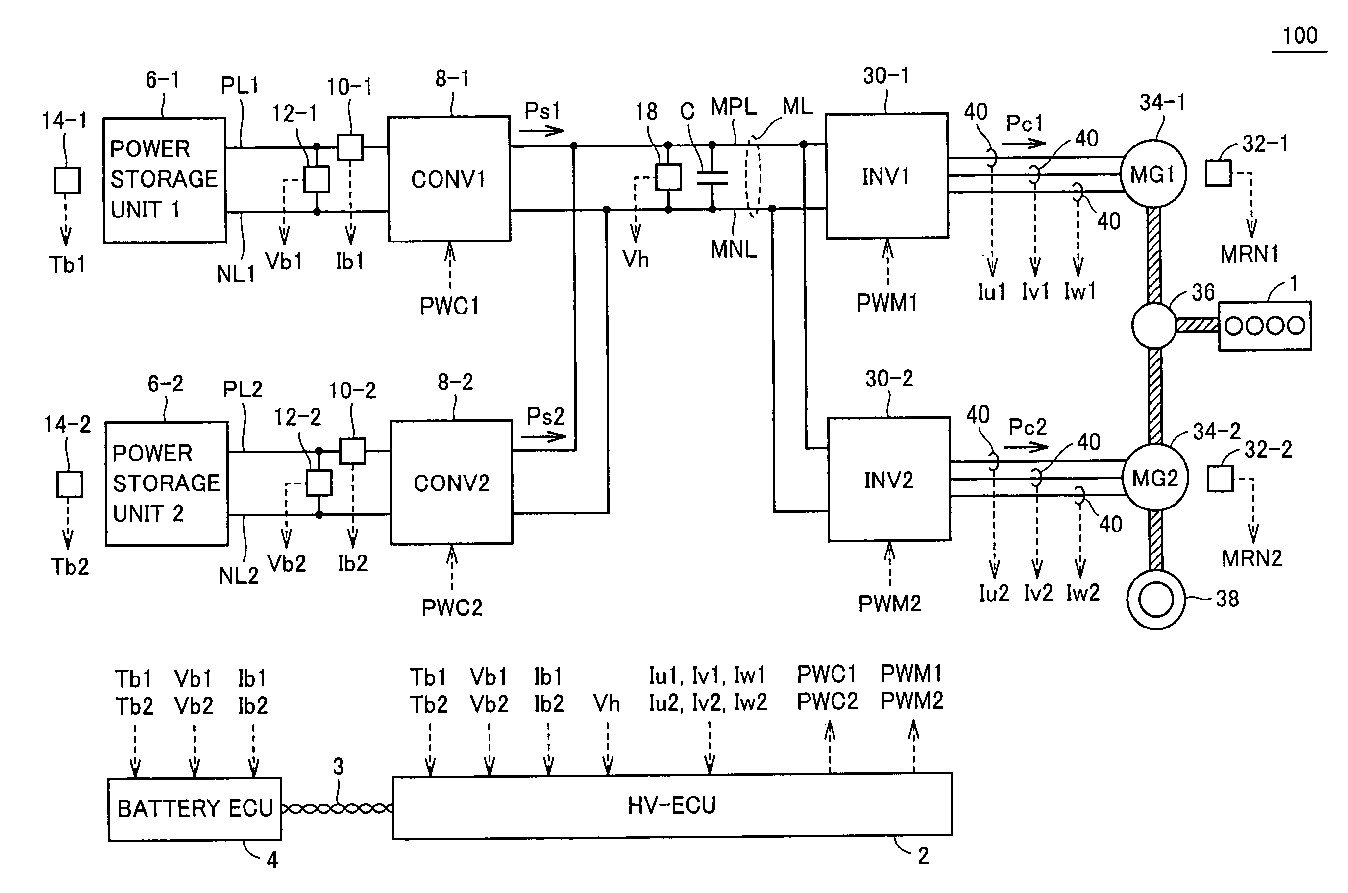
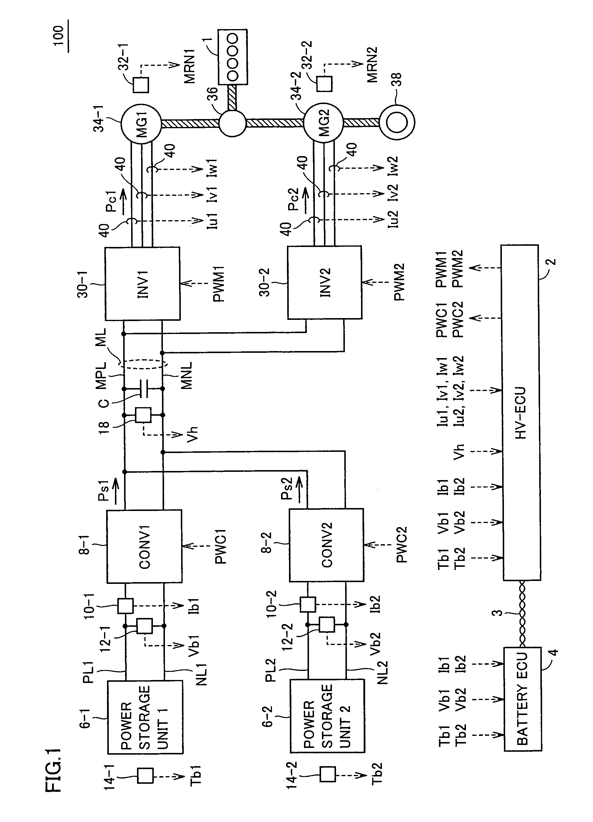
[0039]FIG. 1 is a schematic diagram representing a substantial portion of a vehicle 100 provided with the driving force generation system in accordance with Embodiment 1 of the present invention.

[0040]Referring to FIG. 1, vehicle 100 is, by way of example, a hybrid vehicle using, as driving sources, an engine 1 operating on fuel combustion and a driving force generation system in accordance with the present embodiment, and runs as the generated driving force is transmitted to driving wheels 38. The usage of the driving force generation system in accordance with the present invention is not limited to a hybrid vehicle and it is also applicable to an electric vehicle (EV) not mounting an engine.

[0041]Driving force generation system includes a first power storage unit 6-1, a second power storage unit 6-2, a first converter (CONV1) 8-1, a second converter (CONV2) 8-2, a first inverter (INV1) 30-1, a second inverter (INV2) 30-2, a first motor generator (MG1) 34-1, a second motor generato...

embodiment 2

[0119]FIG. 9 is a schematic diagram showing a substantial portion of a vehicle 100A provided with the driving force generation system in accordance with Embodiment 2 of the present invention.

[0120]Referring to FIG. 9, vehicle 100A corresponds to vehicle 100 shown in FIG. 1 above with converters 8-1 and 8-2 replaced by a single converter 8. Except for the control structure of HV-ECU 2A controlling converter 8, the vehicle is the same as vehicle 100 and, therefore, detailed description of other portions will not be repeated.

[0121]Converter 8 is arranged between power storage units 6-1 and 6-2 and main line ML, and executes the power converting operation. The structure is the same as that of converter 8-1 and, by way of example, it is formed of a “chopper” type voltage step up / down circuit.

[0122]By providing a single converter 8 for the plurality of power storage units 6-1 and 6-2, the space and cost can advantageously be reduced. The charge / discharge power, however, cannot be individu...


PUM


Abstract

A target power value determining unit determines target power values Pc1* and Pc2* such that a sum SPc* of target load powers as a sum of target load power Pc1* and target load power Pc2* does not exceed a sum SWin of allowable charging powers and a sum SWout of allowable discharging powers. In accordance with the generated target load power values Pc1* and Pc2*, switching commands PWM1 and PWM2 are generated. Consequently, an inverter executes a power conversion operation such that the powers exchanged between a main line ML and motor generators attain to the target load power values Pc1* and Pc2*, respectively.

Description

TECHNICAL FIELD[0001]The present invention relates to a driving force generation system having a plurality of power storage units, a vehicle provided with the system, and to a method of controlling the system. Particularly, the present invention relates to a power management technique for the overall system.BACKGROUND ART[0002]Recently, in consideration of environmental issues, vehicles using electric motors as driving sources, such as electric vehicles, hybrid vehicles and fuel cell vehicles are attracting attention. Such a vehicle is provided with a rechargeable power storage unit for supplying power to the electric motor and for converting kinetic energy to electric energy and storing the same at the time of regenerative braking.[0003]In the vehicle having an electric motor as the driving source as described above, power supply of larger capacity is desirable in order to improve running performance such as acceleration characteristic and mileage per charge. As a method of increas...

Claims


Application Information

Patent Timeline
Patent Type & Authority Patents(United States)
IPC IPC(8): B60L1/00B60L9/18B60L50/13B60L50/15B60L50/16H02P21/00H02P21/22H02P25/22H02P27/06H02P27/08
CPCB60L11/1868B60L11/08B60L11/12B60L11/14B60L11/1803B60L11/1859B60L11/1861B60L11/1864B60L15/025B60L11/1862B60L11/1866H02J1/14H02J7/1423H02J7/1453H02J7/1492B60L15/2045Y02T10/92Y02T10/7005Y02T10/7066Y02T10/7283B60L2240/44B60L2240/52B60L2210/10B60L2210/40B60L2220/42B60L2240/423B60L2240/529B60L2240/527Y02T10/7077Y02T10/7044Y02T10/7241Y02T10/7022Y02T10/7061Y02T10/643Y02T10/7216Y02T10/648H02J2007/143B60L50/61B60L50/16B60L50/51B60L58/14B60L58/13B60L58/21B60L58/22B60L58/20H02J7/143H02J2310/48H02J7/007194B60L58/15Y02T10/64Y02T10/62Y02T10/70Y02T10/72Y02T10/7072
Inventor ICHIKAWA, SHINJI
Owner TOYOTA JIDOSHA KK
Why Eureka
Try Eureka