
Methods and systems for diagnosing stator windings in an electric motor

a technology of stator windings and diagnostic methods, which is applied in the direction of dynamo-electric machine testing, instruments, measurement devices, etc., can solve the problems of stator windings that and the stator windings are not suitable for testing

Inactive Publication Date: 2011-11-08
GM GLOBAL TECH OPERATIONS LLC
View PDF23 Cites 64 Cited by
  • Summary
  • Abstract
  • Description
  • Claims
  • Application Information

AI Technical Summary

Benefits of technology

The patent describes a method and apparatus for identifying and diagnosing fault conditions in stator windings of an electric motor. The method involves applying a signal to the stator windings and measuring the response, while the apparatus includes a current sensor and control module for applying an injection voltage signal and measuring the current. The technical effects of this patent include improved identification and diagnosis of motor faults, improved efficiency of motor maintenance, and improved performance and reliability of electric vehicles.

Problems solved by technology

However, over time, the operating stresses applied to the electric motor may degrade the condition of the stator windings.
For example, thermal stress and / or voltage stress may lead to insulation breakdown, which in turn, may result in partial short-circuiting and / or open-circuiting of individual turns of the stator windings.
However, difficulties arise for certain machine types.
Even for synchronous machines without an inherent saliency, such as a surface mount permanent magnet machine, secondary effects such as saturation often result in significant saliency which can cause the same effect described above.
Similarly, this technique is not suitable for zero speed or low speed operation, as the motor harmonics converge to zero.
However, this technique relies on a rotating electric field to detect the current imbalance, and is not suitable for zero speed or low speed operation.
Thus, the prior art techniques are generally ineffective for stationary motors during start-up conditions, i.e., at zero or low rotor speed.
In these situations, to detect the presence of a fault condition, the potentially faulty electric motor must be started and / or operated to detect the fault condition, which is counterintuitive and undesirable.

Method used


Image

  • Methods and systems for diagnosing stator windings in an electric motor
  • Methods and systems for diagnosing stator windings in an electric motor
  • Methods and systems for diagnosing stator windings in an electric motor

Examples


Embodiment Construction

[0014]The following detailed description is merely illustrative in nature and is not intended to limit the embodiments of the subject matter or the application and uses of such embodiments. As used herein, the word “exemplary” means “serving as an example, instance, or illustration.” Any implementation described herein as exemplary is not necessarily to be construed as preferred or advantageous over other implementations. Furthermore, there is no intention to be bound by any expressed or implied theory presented in the preceding technical field, background, brief summary or the following detailed description.

[0015]Techniques and technologies may be described herein in terms of functional and / or logical block components, and with reference to symbolic representations of operations, processing tasks, and functions that may be performed by various computing components or devices. It should be appreciated that the various block components shown in the figures may be realized by any numb...


PUM


Abstract

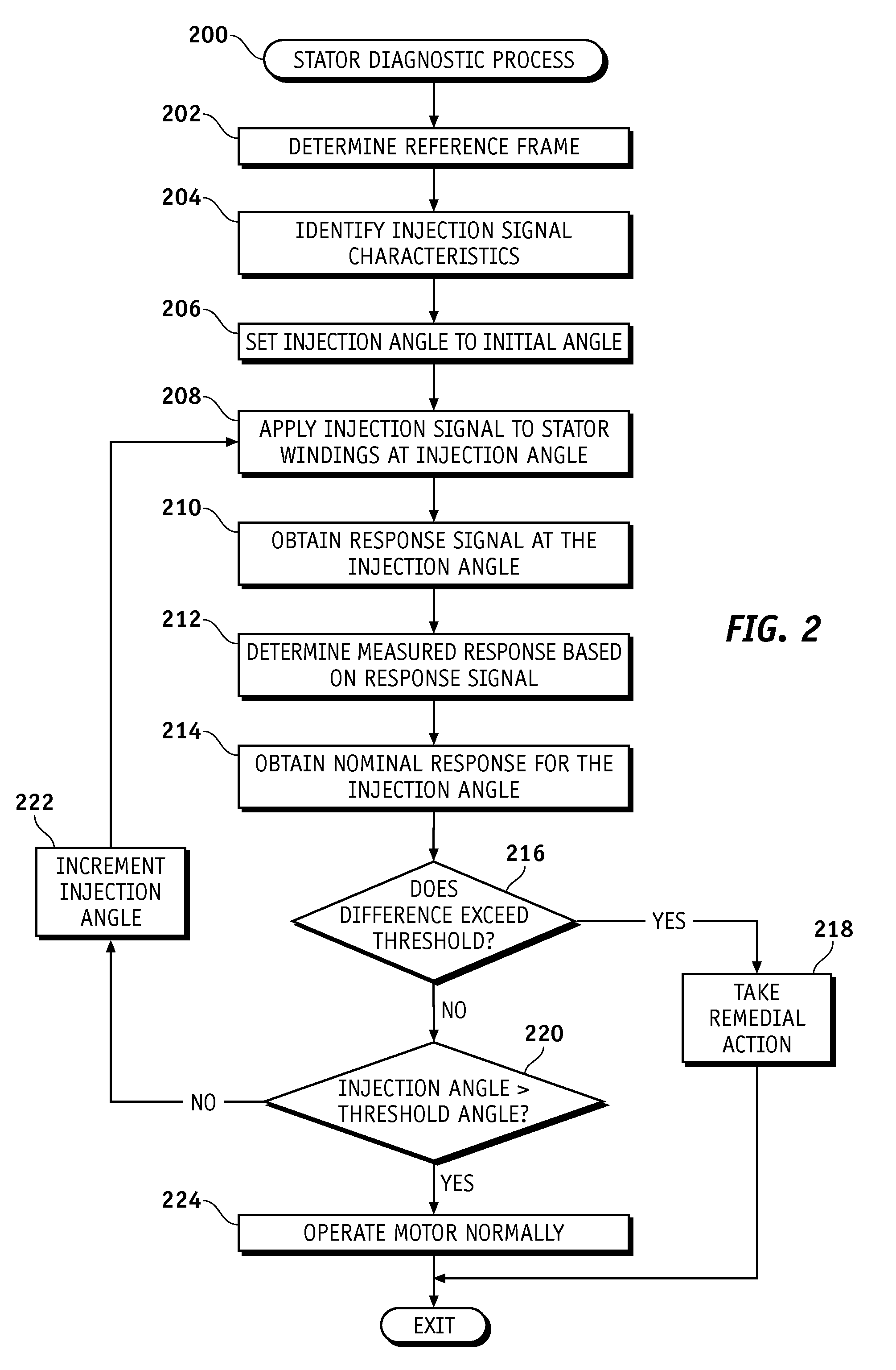
Systems and methods are provided for identifying a fault condition in stator windings in an electric motor. A method comprises applying a first signal at a first electrical angle to the stator windings and measuring a second signal from the stator windings in response to the first signal. The method further comprises determining a measured response for the electric motor at the first electrical angle based on the second signal and obtaining a nominal response for the electric motor at the first electrical angle. A fault condition is identified when a magnitude of the difference between the measured response and the nominal response is greater than a threshold value.

Description

TECHNICAL FIELD[0001]Embodiments of the subject matter described herein relate generally to electrical systems in automotive vehicles, and more particularly, embodiments of the subject matter relate to systems and methods for diagnosing a fault condition in stator windings of an electric motor.BACKGROUND[0002]In recent years, advances in technology, as well as ever evolving tastes in style, have led to substantial changes in the design of automobiles. Electric motors (or electric machines) are finding an increasing number of applications in the automotive industry due to the electrification of the automotive drive system. Electric and / or hybrid vehicles utilize electric motors as either primary or supplemental torque sources in the automotive drive system. These electric motors are expected to function over extreme operating conditions for an extended period of time with high reliability. However, over time, the operating stresses applied to the electric motor may degrade the condit...

Claims


Application Information

Patent Timeline
Patent Type & Authority Patents(United States)
IPC IPC(8): G01R31/06G01R31/50
CPCG01R31/346G01R31/024G01R31/34G01R31/50
Inventor SCHULZ, STEVEN E.RAHMAN, KHWAJA M.YEH, CHIA-CHOU
Owner GM GLOBAL TECH OPERATIONS LLC
Learn More