Carbon monoxide detector, system and method for signaling a carbon monoxide sensor end-of-life condition

a carbon monoxide sensor and end-of-life technology, applied in the direction of fire alarms, smoke/gas actuation, instruments, etc., can solve the problem of saving expense by knowing the difference between an end-of-life signal and a standard trouble signal. , to achieve the effect of saving expens

Active Publication Date: 2011-11-08
WALTER KIDDE PORTABLE EQUIP
View PDF13 Cites 12 Cited by
  • Summary
  • Abstract
  • Description
  • Claims
  • Application Information

AI Technical Summary

Benefits of technology

[0007]Systems and methods are provided herein that allow a carbon monoxide (CO) detector to transmit a signal representative of an end-of-life of a sensor in the CO detector, and further, allows a monitoring agency to differentiate the end-of life signal from standard trouble signals. Therefore, knowing a difference between an end-of-life signal and a standard trouble signal saves expense by knowing what service calls need addressing immediately and what service calls are not as immediate. For example, an end-of-life signal, which requires a service call, the immediacy of a service call for an end-of-life signal is not as immediate as a service call that stems from a standard trouble signal.

Problems solved by technology

Therefore, knowing a difference between an end-of-life signal and a standard trouble signal saves expense by knowing what service calls need addressing immediately and what service calls are not as immediate.

Method used


Image

  • Carbon monoxide detector, system and method for signaling a carbon monoxide sensor end-of-life condition
  • Carbon monoxide detector, system and method for signaling a carbon monoxide sensor end-of-life condition
  • Carbon monoxide detector, system and method for signaling a carbon monoxide sensor end-of-life condition

Examples


Embodiment Construction

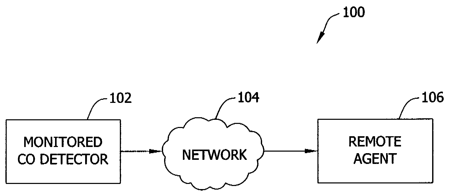
[0015]Referring initially to FIG. 1, a block diagram of an exemplary system architecture is shown and designated generally as system 100. The system 100 is but one example of a suitable system and is not intended to suggest any limitation as to the scope of use or functionality of the present disclosure.

[0016]Embodiments of the present disclosure enable a carbon monoxide (CO) detector, such as a monitored CO detector 102 in FIG. 1, to communicate with a remote agent 106 via a network 104. In the exemplary embodiment, the monitored CO detector 102 may be a conventional CO detector or an addressable CO detector. A conventional CO detector provides static outputs for alarm and trouble. In one embodiment, the static outputs take the form of relay outputs that show a change of state for a change of status (e.g., alarm or trouble). In a further embodiment, an addressable CO detector uses a communications protocol over many forms of media (e.g., wireless, two wire, power line, and the like...


PUM


Abstract

A CO detector includes a sensor configured to detect a presence of CO and generate a signal indicative of the presence of CO, and a controller in signal communication with the sensor. The controller is configured to measure a level of detected CO in response to receiving the signal generated by the sensor. The controller is further configured to detect a first trouble condition representative of an end-of-life condition of the sensor, and a second trouble condition different from the first trouble condition.

Description

BACKGROUND THE INVENTION[0001]1. Field of the Invention[0002]The embodiments described herein relate generally to signaling an end-of-life of a carbon monoxide (CO) sensor and, more particularly, to a method and system for transmitting a CO sensor end-of-life signal of a sensor to a remote agent.[0003]2. Description of the Prior / Related Art[0004]Carbon monoxide (CO) is an odorless, poisonous gas, which can be generated by, for example, gas furnaces, water heaters, ranges, space heaters, wood stoves, cars, portable generators, and gas-powered gardening equipment. Once inhaled, CO inhibits red blood cells from carrying oxygenated blood to the body, thus preventing oxygen from reaching organs in the body. This oxygen deprivation can cause varying amounts of damage depending on a level of exposure. Low level exposure can cause flu-like symptoms including shortness of breath, mild headaches, fatigue, and nausea. However, higher level exposure may cause dizziness, mental confusion, severe...

Claims


Application Information

Patent Timeline
Patent Type & Authority Patents(United States)
IPC IPC(8): G08B17/10G08B21/00
CPCG08B29/04G08B21/14
Inventor HARKINS, MICHAEL T.BARNES, BRADLEY B.
Owner WALTER KIDDE PORTABLE EQUIP
Why Eureka
Try Eureka