Speedometer for train crossings

a technology for speedometers and trains, applied in the direction of identification means, instruments, signs, etc., can solve the problems of high mortality rates, complicated safety systems, and vehicular accidents, and achieve the effect of reducing the number of accidents

Inactive Publication Date: 2011-11-08
MARTIN CHRIS +1
View PDF1 Cites 12 Cited by
  • Summary
  • Abstract
  • Description
  • Claims
  • Application Information

AI Technical Summary

Benefits of technology

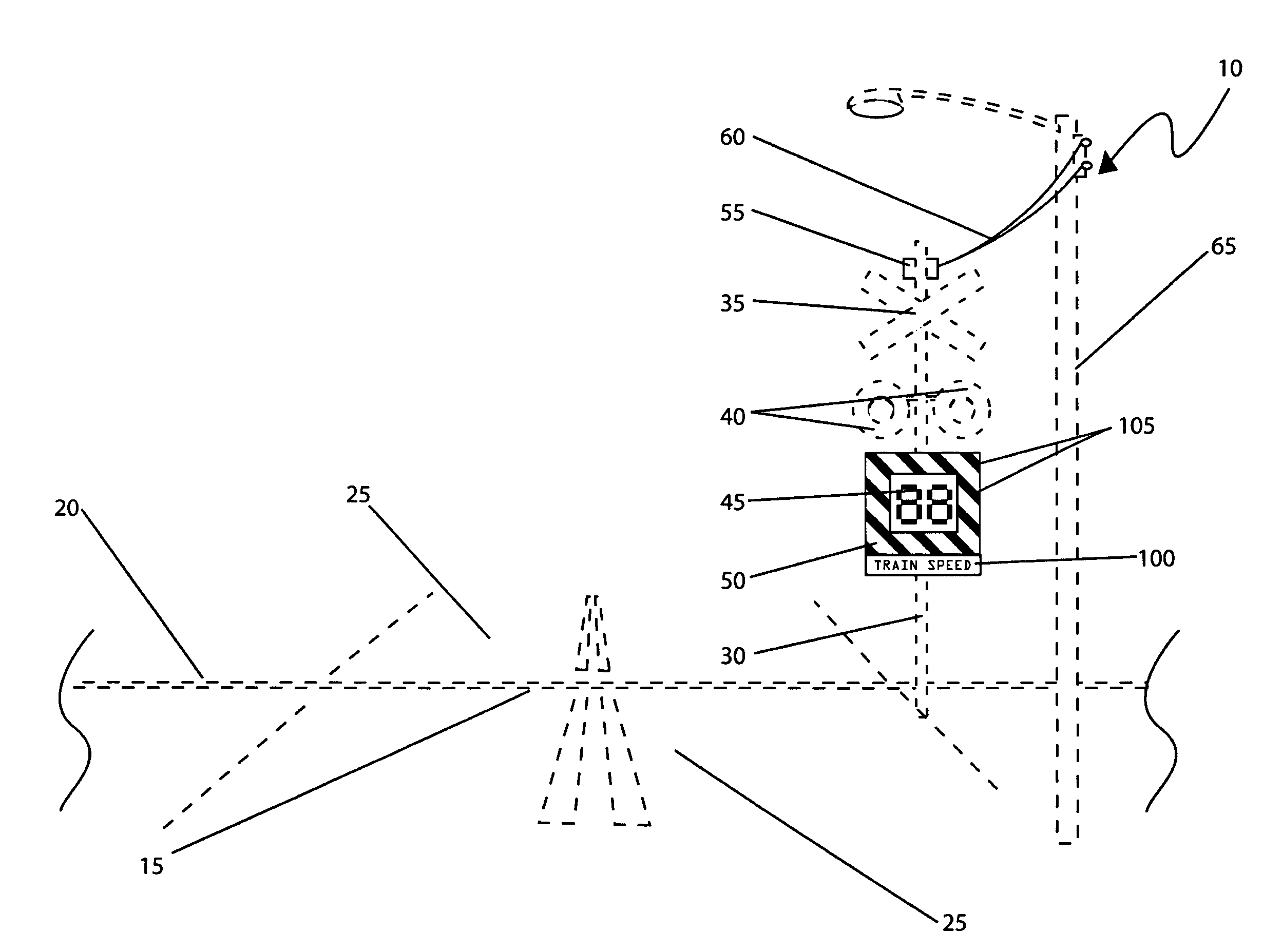
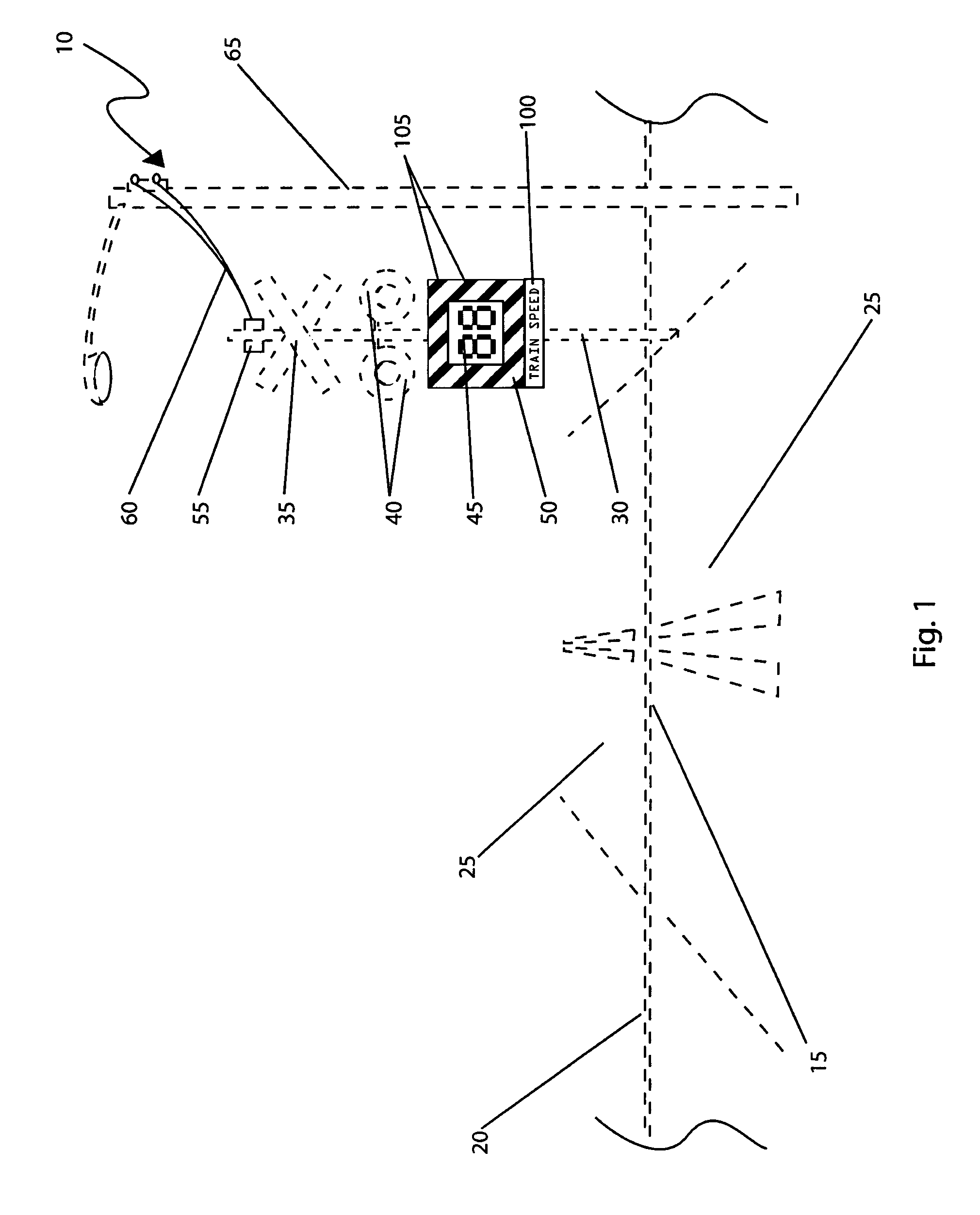
[0008]To achieve the above objectives, it is an object of the present invention to provide a speed indication device for approaching trains at railroad crossings that provides a means for displaying the speed of an approaching train on a conventional railroad crossing, thereby preventing motorists from trying to outrun oncoming trains and causing accidents.
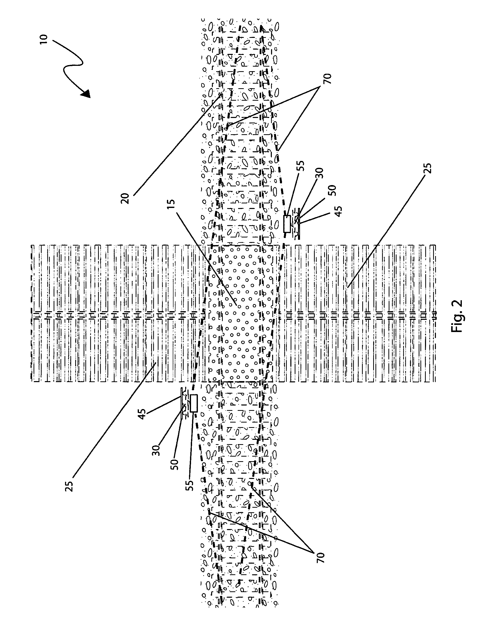
[0009]Another object of the speed indication device for approaching trains at railroad crossings is to provide a system comprises a digital speed display, a speed warning sign, a control enclosure, a power drop, a speed detection beam, a power supply, a rechargeable battery, a speed detection circuit, a speed detection means, and a digital display driver. The speed warning sign provides various visual indicia to draw the attention of a motorist to the digital speed display which indicates the speed of an approaching train using the appropriate unit of measurement per local requirements. Thus with a conventional pair of crossing lights energized and the speed of an oncoming train displayed upon the digital speed display, motorists would be less likely to attempt to “beat” the train across the railroad crossing. After the train has passed, the system continuously monitors the train track for other trains.

Problems solved by technology

Automobiles struck by trains at railroad crossings usually result in higher mortality rates than other vehicular accidents.
More complicated safety systems also exist from automated warning and access systems to satellite alert systems.
These systems can be expensive and require regular maintenance to ensure effectiveness.
However, many motorists are poor judges of speed or may not have an actual view of the train due to limited line of sight position.

Method used


Image

  • Speedometer for train crossings
  • Speedometer for train crossings
  • Speedometer for train crossings

Examples


Embodiment Construction

[0058]The best mode for carrying out the invention is presented in terms of its preferred embodiment, herein depicted within FIGS. 1 through 5 and alternately within FIGS. 6 and 7. However, the invention is not limited to the described embodiment and a person skilled in the art will appreciate that many other embodiments of the invention are possible without deviating from the basic concept of the invention, and that any such work around will also fall under scope of this invention. It is envisioned that other styles and configurations of the present invention can be easily incorporated into the teachings of the present invention, and only one particular configuration shall be shown and described for purposes of clarity and disclosure and not by way of limitation of scope.

[0059]The terms “a” and “an” herein do not denote a limitation of quantity, but rather denote the presence of at least one of the referenced items.

[0060]The present invention describes a speed indication device for...


PUM


Abstract

An apparatus that indicates the speed of oncoming trains at train crossings comprises a large digital display attached to a drop gate or alternately on a side gate crossing sign for those crossings without a gate. The digital display is surrounded by a large sign indicating the speed of an oncoming train. A speed detection device aimed in either direction on the track to determine train speed. An interface converts the detected speed into a digital display. It is envisioned that motorists knowing the speed of an oncoming train will be less likely to try to beat the train through the crossing.

Description

RELATED APPLICATIONS[0001]The present invention was first described in and claims the benefit of U.S. Provisional Application No. 61 / 130,251, filed May 30, 2008, the entire disclosures of which are incorporated herein by reference.FIELD OF THE INVENTION[0002]The present invention relates generally to railroad crossing alert and safety systems and, more particularly, to an indicator for railroad crossings which indicates the speed of an oncoming train.BACKGROUND OF THE INVENTION[0003]Automobile accidents are among the leading causes of death in the United States. Many thousands of railroad crossings intersecting with vehicle roadways exist and the importance of providing adequate and reliable information regarding an oncoming train is crucial to protect motorists. Automobiles struck by trains at railroad crossings usually result in higher mortality rates than other vehicular accidents. These accidents are also among the easiest to prevent. Typically, railroad crossing guards are acti...

Claims


Application Information

Patent Timeline
Patent Type & Authority Patents(United States)
IPC IPC(8): G09F9/00G08G1/09B61L9/00
CPCB61L25/021B61L29/24B61L29/32G09F2007/1813G09F2007/1878G09F2013/0472G09F13/0472
Inventor MARTIN, CHRISMARTIN, TAMMY
Owner MARTIN CHRIS
Why Eureka
Try Eureka