Vacuum relief unit and method for a pool
a vacuum relief and pool technology, applied in the direction of fluid pressure control, process and machine control, instruments, etc., can solve the problem of not unnecessarily venting enough air into the pumping system to lose prime, and achieve the effect of convenient installation and simple installation
- Summary
- Abstract
- Description
- Claims
- Application Information
AI Technical Summary
Benefits of technology
Problems solved by technology
Method used
Image
Examples
Embodiment Construction
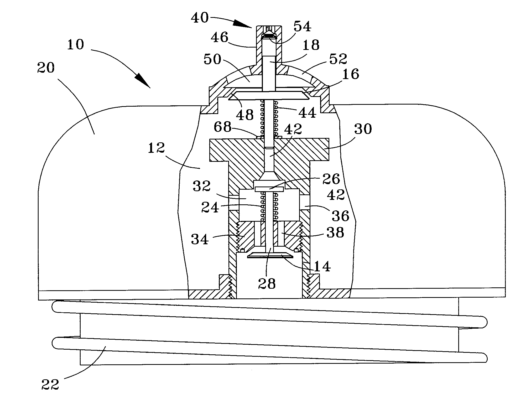
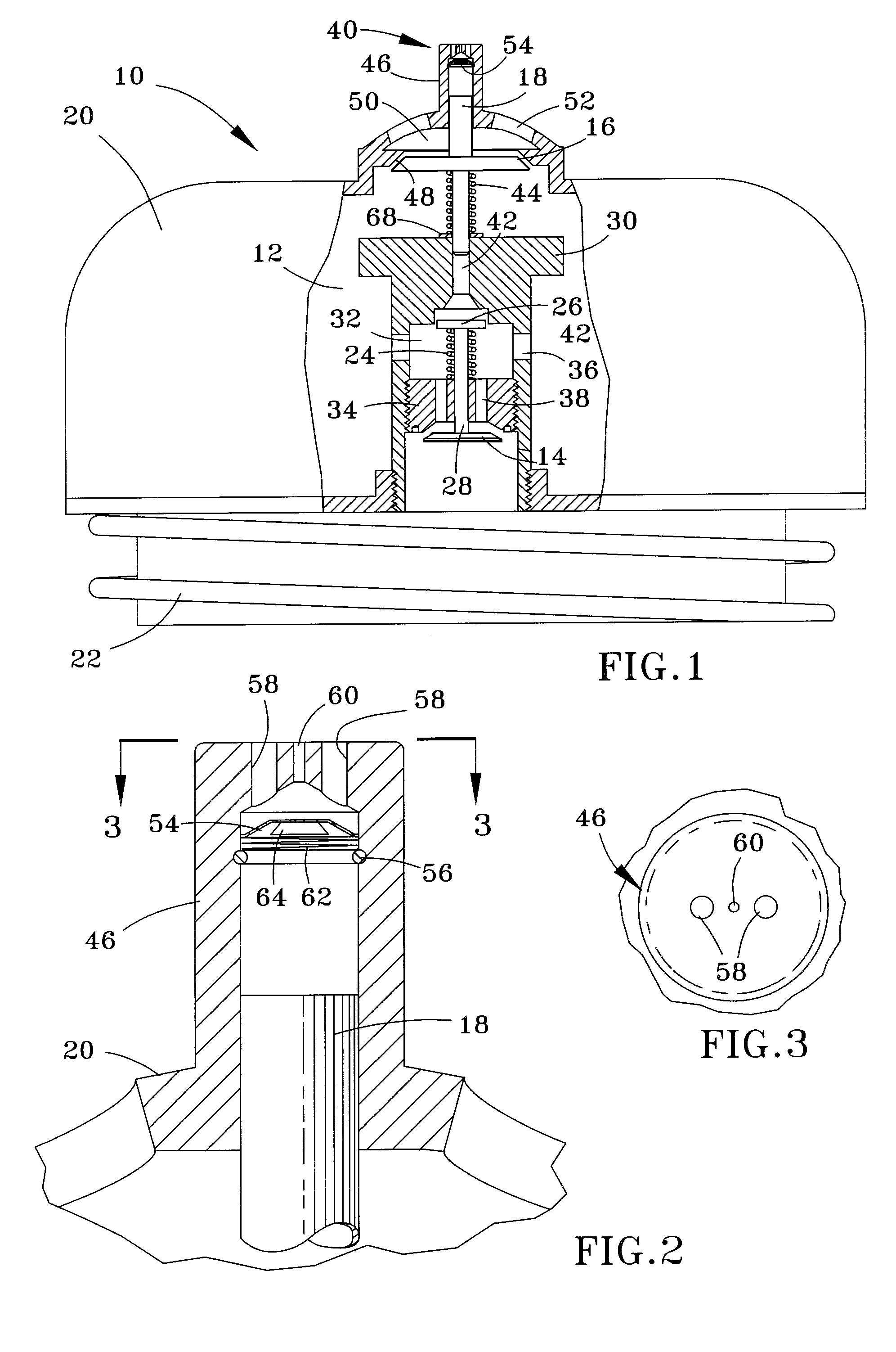
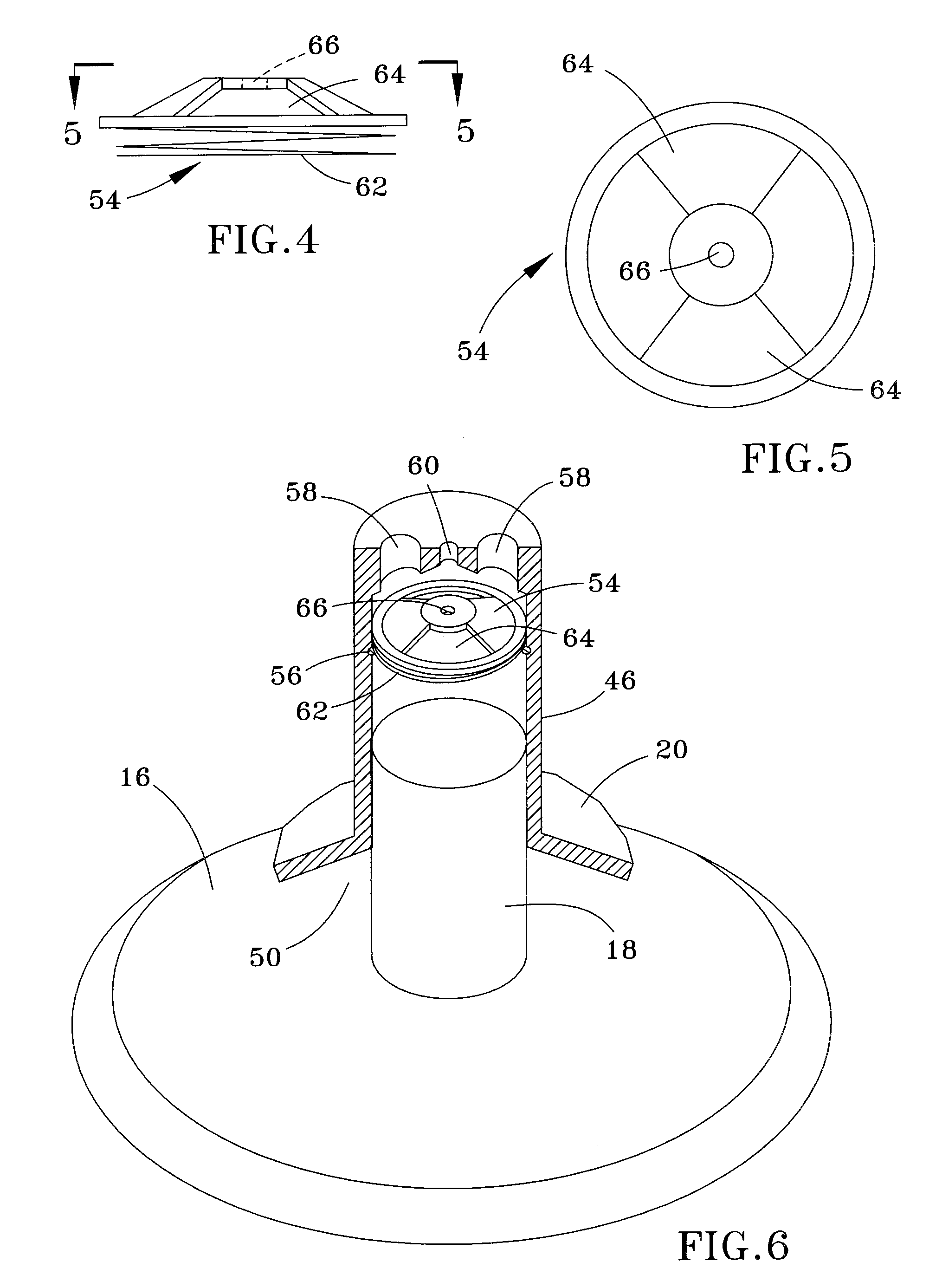
[0016]A vacuum relief unit 10 is represented in the Figures as comprising an air chamber 12 defined by a dome-shaped housing 20, two diaphragms 14 and 16 that operate in series within the housing 20, and a piston 18 also within the housing 20. The housing 20 is configured to be installed in the cover of a pool lint trap (not shown) connected to a pumping system of a pool, hot tub, etc., and is provided with threads 22 at a lower end thereof to permit the housing 20 to be threaded into an opening formed in a conventional lint trap cover. However, it should be understood that the unit 10 is not limited to this type of installation.
[0017]From FIG. 1, it is evident that the first and second diaphragms 14 and 16 are not mechanically coupled to each other. The first diaphragm 14 operates to seal the chamber 12 from a suction line of a pool (not shown) to which the lint trap is connected, and only opens to permit venting of air within the chamber 12 to the suction line if a sufficiently lo...
PUM
 Abstract
Description
Claims
Application Information
 - R&D
- Intellectual Property
- Life Sciences
- Materials
- Tech Scout
- Unparalleled Data Quality
- Higher Quality Content
- 60% Fewer Hallucinations
Browse by: Latest US Patents, China's latest patents, Technical Efficacy Thesaurus, Application Domain, Technology Topic, Popular Technical Reports.
© 2025 PatSnap. All rights reserved.Legal|Privacy policy|Modern Slavery Act Transparency Statement|Sitemap|About US| Contact US: help@patsnap.com


