Telescopic strut for an external fixator

a technology of fixator and telescopic strut, which is applied in the field of telescopic strut for an external fixator, can solve problems such as difficulty in adjustmen

Active Publication Date: 2011-11-15
STRYKER EURO OPERATIONS HLDG LLC
View PDF68 Cites 65 Cited by
  • Summary
  • Abstract
  • Description
  • Claims
  • Application Information

AI Technical Summary

Benefits of technology

[0005]However, these devices, which can be used to shorten or lengthen the telescopic struts, are difficult to adjust and it is one object of the invention to improve the ease of adjusting the length of the rod.
[0006]Based on the prior art, it is therefore an object of the invention to provide a telescopic strut, which can be readily and quickly changed in its length.
[0008]In view of the above mentioned aspect it is furthermore another aspect of the invention to allow a quick switch between the two functions, i.e. to allow a quick first definition of the length of the telescopic element, and additionally, to switch for a fine adjustment of said length.

Problems solved by technology

However, these devices, which can be used to shorten or lengthen the telescopic struts, are difficult to adjust and it is one object of the invention to improve the ease of adjusting the length of the rod.

Method used


Image

  • Telescopic strut for an external fixator
  • Telescopic strut for an external fixator
  • Telescopic strut for an external fixator

Examples


Embodiment Construction

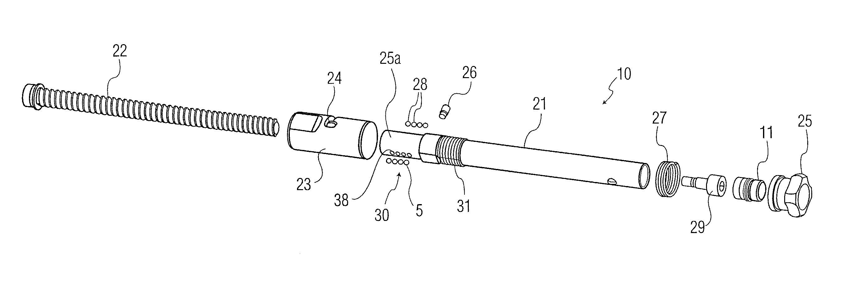
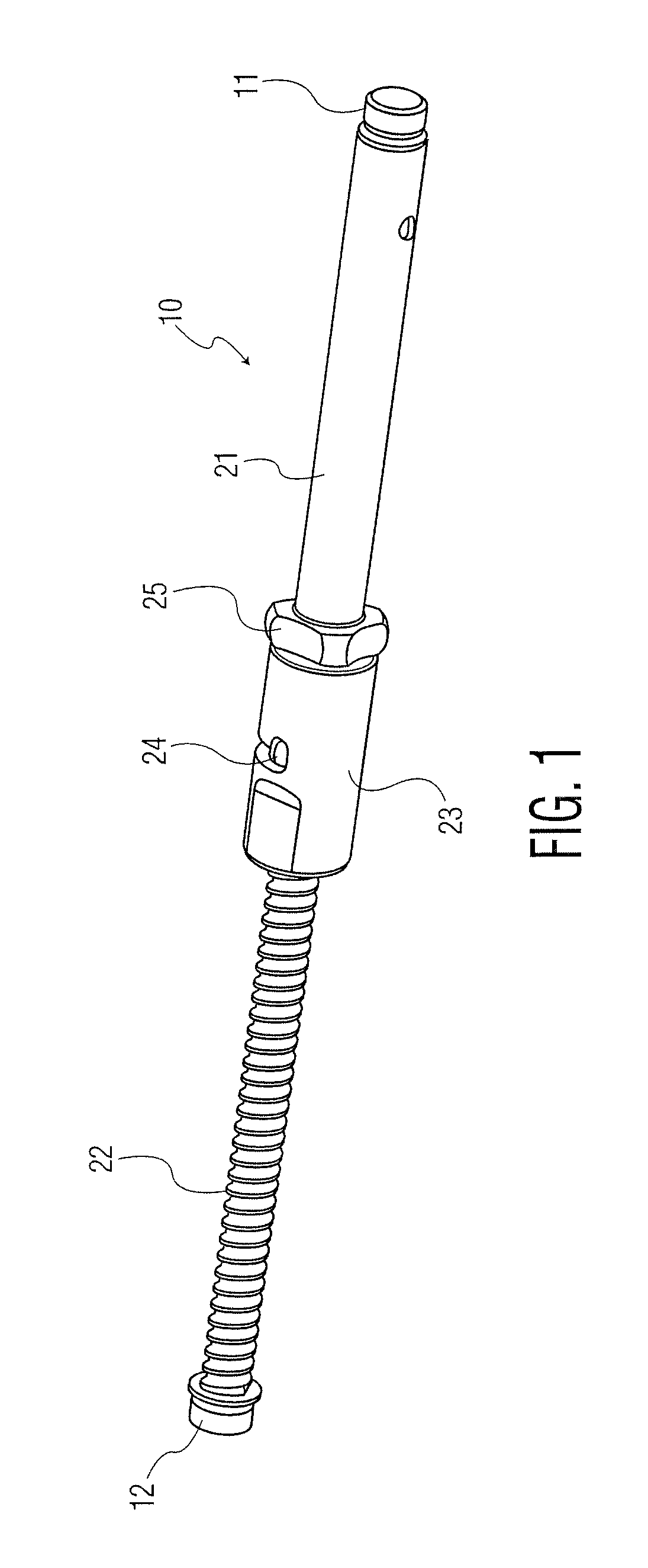
[0014]Referring to FIG. 1 there is shown a perspective view of a telescopic strut according to the invention generally denoted as 10. The telescopic strut comprises two free ends 11 and 12 being attachment points for connecting the rod with two external rings to be placed around the limb to be fixed. The attachment points 11 and 12 according to this embodiment comprise cylindrical knobs, but this entirely depends on the kind of fixation element for which the rod is used.

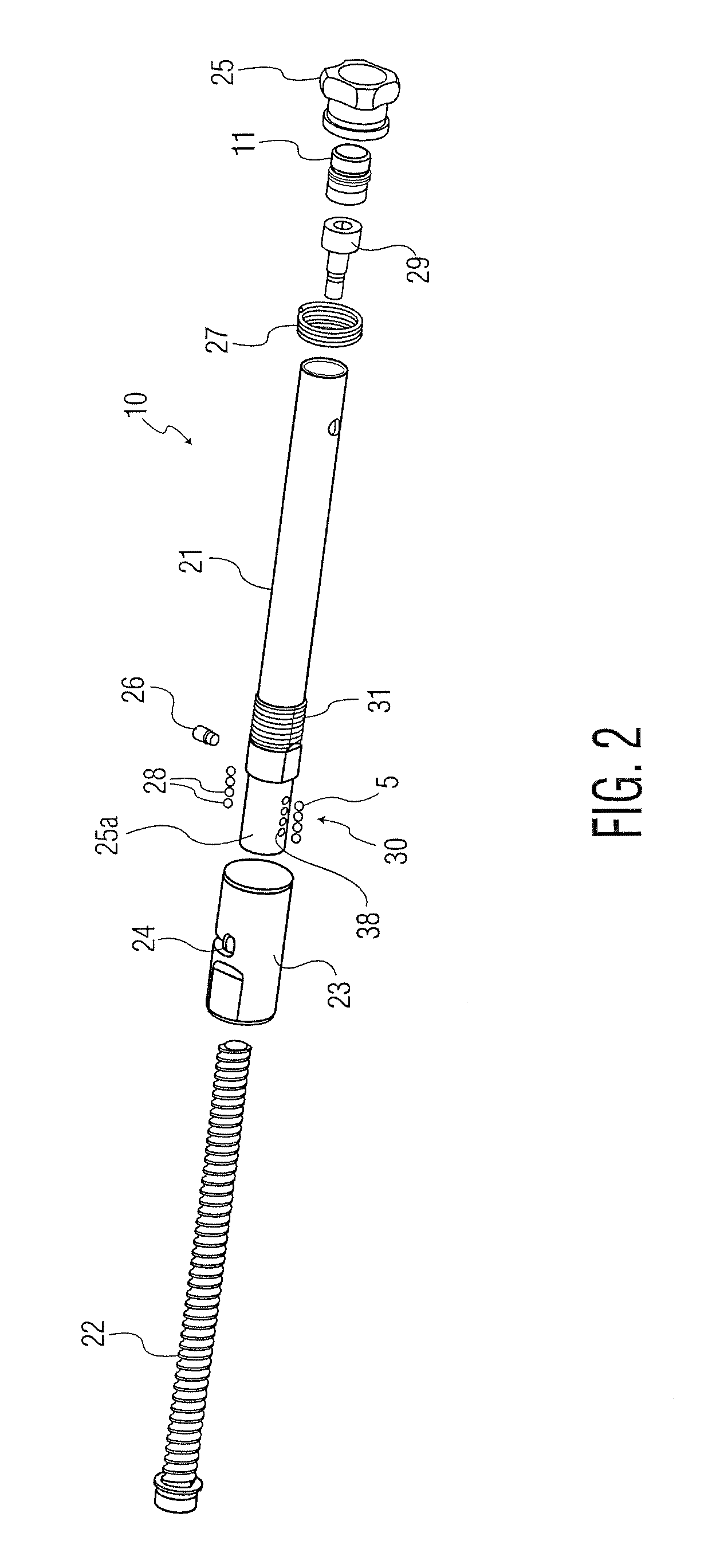
[0015]FIG. 1 shows the main components of the telescopic strut. There is an outer tube 21 in which the threaded rod 22 is partially located. The opposite thread element 30 is located within the sleeve 23 and is better seen in FIG. 2 as well as FIG. 3 and will be described below and comprises balls 28 which ride in the threads of rod 22. In the preferred embodiment sleeve 23 comprises a bayonet groove 24 for a quick change between the desired quick length change mode and the fine adjustment mode. The sleeve 23 can be ...


PUM


Abstract

A telescopic strut for use with an external fixator includes a tube and a rod, especially a threaded rod being in threaded engagement with the tube. The tube comprises at least one hole for accommodating a ball, the ball having the spherical shape for engagement with the threaded rod. A sleeve is provided on the portion of the tube comprising the hole. The sleeve comprises a non-spherical inner cross-section. The greater diameter of the sleeve has a dimension which is at least the sum of the outer diameter of the threaded rod plus the diameter of an accommodating ball for allowing direct axial movement of the threaded rod against the tube in such a rotational position of the sleeve. The lesser diameter has a dimension to place the ball within the threaded rod for allowing a rotational movement of the threaded rod against the tube.

Description

BACKGROUND OF THE INVENTION[0001]The invention relates to a telescopic strut for an external fixator, especially for use with an external ring fixator.[0002]A plurality of compression-distraction apparatus have been designed and improved by Ilizarov and his group using two external rings to be placed around the limb to be fixed. There are usually at least two such rings, one proximal and one distal ring, which are connected with a plurality of struts or rods. Preferably, these struts are linked to the rings in a way that the attachment points can be pivoted and the length of the strut can be varied to enable adjustment of the external fixation rings.[0003]Ilizarov has also provided some improvements for said systems. EP 0 377 744 shows a telescopic strut for such an external fixator. U.S. Pat. No. 4,615,338 shows a further device to control the length of such telescopic struts.[0004]A different external ring fixator having telescopic struts is shown in U.S. Pat. No. 5,702,389.SUMMAR...

Claims


Application Information

Patent Timeline
Patent Type & Authority Patents(United States)
IPC IPC(8): A61F5/04
CPCA61B17/62A61B17/6458
Inventor KNUCHEL, BEATBURGHERR, VINZENZSTEINER, CHRISTIANFIECHTER, MEINRAD
Owner STRYKER EURO OPERATIONS HLDG LLC
Why Eureka
Try Eureka