Electrowetting display devices

Active Publication Date: 2011-11-15
IND TECH RES INST
View PDF14 Cites 56 Cited by
  • Summary
  • Abstract
  • Description
  • Claims
  • Application Information

AI Technical Summary

Problems solved by technology

A part of the incident light is absorbed by the color filter, lowering the optical performance of the display due to the light absorption of the color filter.
In addition, alignment between the color filter substrate and the lower sub

Method used


Image

  • Electrowetting display devices
  • Electrowetting display devices
  • Electrowetting display devices

Examples


Embodiment Construction

[0023]It is to be understood that the following disclosure provides many different embodiments, or examples, for implementing different features of various embodiments. Specific examples of components and arrangements are described below to simplify the present disclosure. These are merely examples and are not intended to be limiting. In addition, the present disclosure may repeat reference numerals and / or letters in the various examples. This repetition is for the purpose of simplicity and clarity and does not in itself indicate a relationship between the various embodiments and / or configurations discussed. Moreover, the formation of a first feature over or on a second feature in the description that follows may include embodiments in which the first and second features are formed in direct contact or not in direct contact.

[0024]Embodiments of the invention are directed to electrowetting devices for which display is achieved by electrically changing surface characteristics of polar...


PUM


Abstract

Electrowetting devices (EWD) are presented. The electrowetting device includes a first substrate and an opposing second substrate with a polar fluid layer and a non-polar fluid layer interposed therebetween. A first transparent electrode is disposed on the first substrate. A second electrode is disposed on the second substrate. A first partition structure is disposed on the first substrate; thereby defining a plurality of color sub-pixels. A dye and/or a pigment substance is doped in one of the polar fluid layer and the non-polar fluid layer. A luminescence substance is doped in one of the polar fluid layer and the non-polar fluid layer. An emission module (also known as an excitation module) is disposed underlying the bottom of the first substrate. The colors of the non-polar fluid layer in the neighboring sub-pixels are different.

Description

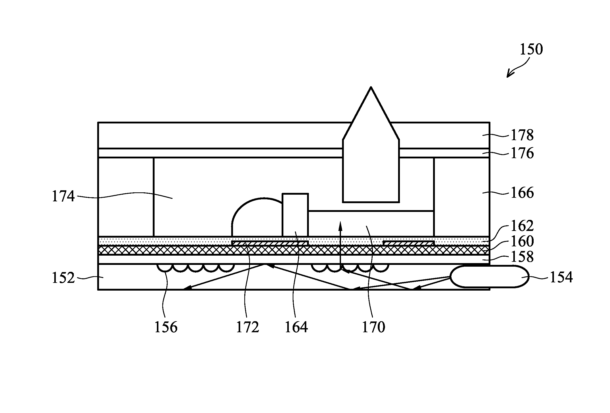
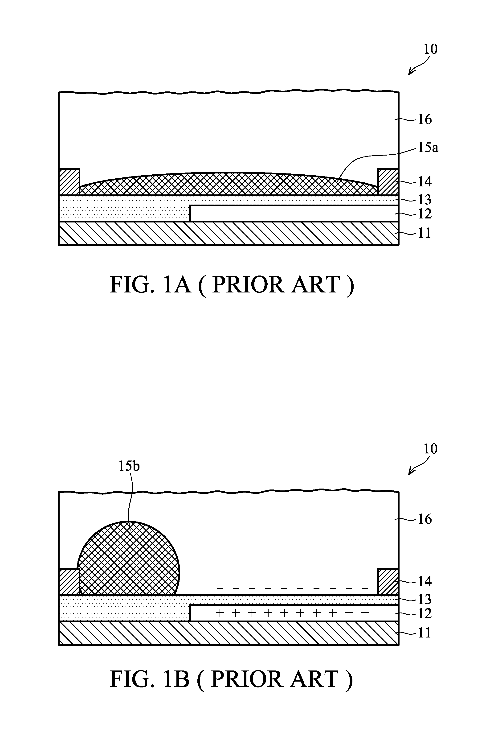
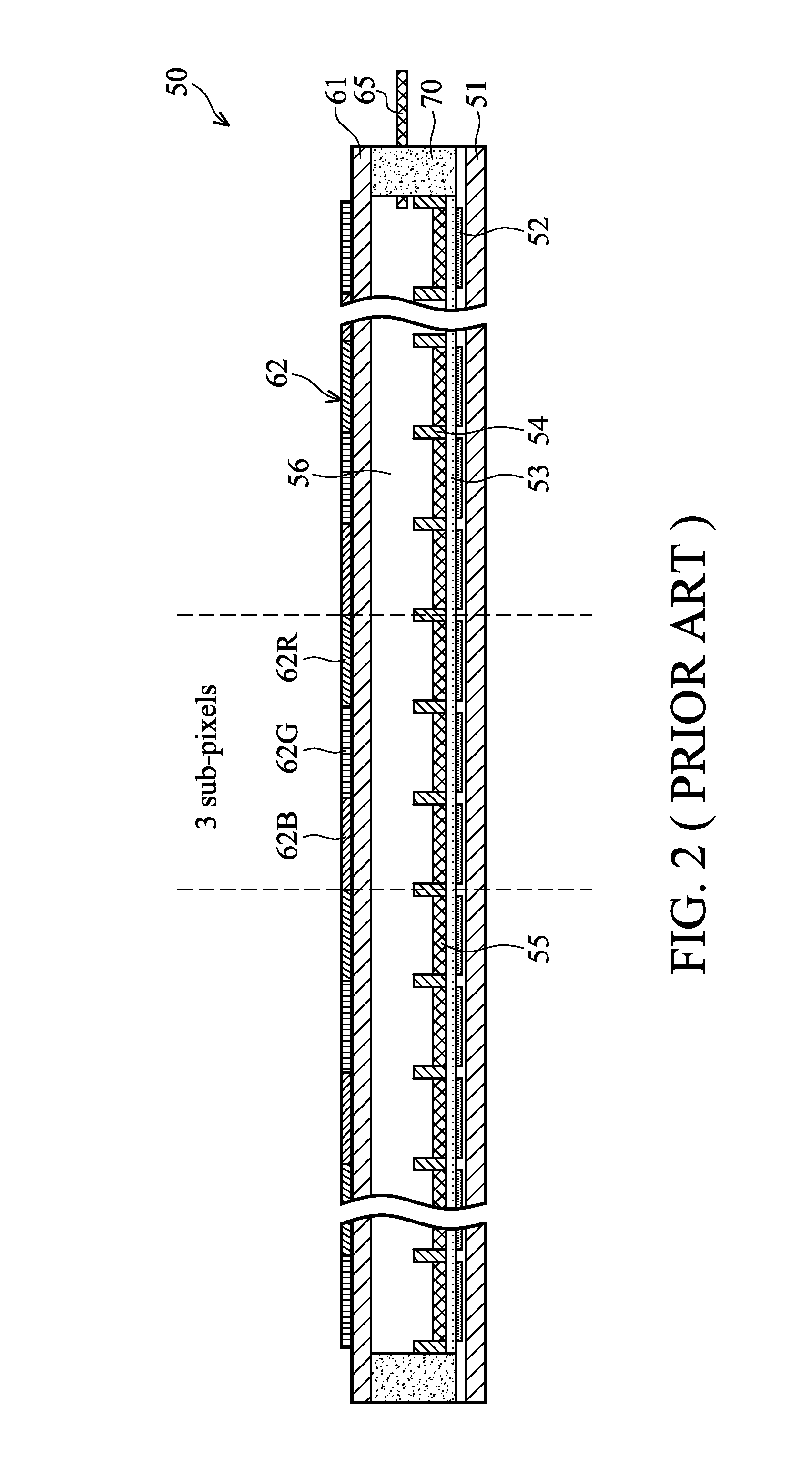
BACKGROUND OF THE INVENTION[0001]1. Field of the Invention[0002]The invention relates to electrowetting devices.[0003]2. Description of the Related Art[0004]Electrowetting display devices are rendered images in accordance with electrowetting or electrocapillary techniques. Briefly, the free surface energy of some fluids is changed due to the electric field effects such that distribution area of the fluids can change along with the electric field effects.[0005]U.S. Pat. No. 6,967,763, the entirety of which is hereby incorporated by reference, discloses an electrowetting display device. A non-polar fluid in the electrowetting display device converges due to the electrowetting effect; thereby controlling a bright state and / or a dark state of a pixel.[0006]FIGS. 1A and 1B are cross sections respectively illustrating a voltage off-state and a voltage on-state for a conventional electrowetting display. Referring to FIG. 1A, a conventional electrowetting display 10 includes a substrate 11 ...

Claims


Application Information

Patent Timeline
IPC IPC(8): G02B26/00
CPCG02B26/005
Inventor KUO, SHU-WEISHIU, JYH-WENCHENG, WEI-YUANKU, YUN-SHENG
Owner IND TECH RES INST
Why Eureka
Try Eureka