Creating task queries for concrete resources using alias selection fields specifying formal resources and formal relationships

a task and task query technology, applied in the field of information technology, can solve the problems of affecting the performance of the scheduler, consuming a lot of time, and unable to identify the actual resources that meet the above-mentioned conditions,

Inactive Publication Date: 2011-11-15
INT BUSINESS MASCH CORP
View PDF14 Cites 5 Cited by
  • Summary
  • Abstract
  • Description
  • Claims
  • Application Information

AI Technical Summary

Problems solved by technology

The identification of the actual resources that satisfy the above-mentioned conditions is quite complex.
However, the above-described iterative method is very time consuming.
This has a detrimental effect on the performance of the scheduler.
As an extreme case, the application of the proposed solution may even be not feasible in specific environments (with very strict time constraints).
Moreover, the relatively long time required by the iterative method does not allow ensuring the consistency of the information that is used during the whole process (for example, because the resources have changed in the meanwhile).
Therefore, it is impossible to guarantee the integrity of the results being obtained.
This can cause errors in the executions of the jobs (for example, when some jobs are submitted on execution servers that do not have the required resources actually).
This is very serious when the error affects a critical job (on which many other jobs depend for their execution); as a result, the execution of the whole plan (or at least of a substantial part thereof) may be blocked.
All of the above hinders the widespread application of the proposed solution; this drawback is more acute in environments where its implementation would be particularly useful (for example, in distributed systems—especially based on the Internet).

Method used


Image

  • Creating task queries for concrete resources using alias selection fields specifying formal resources and formal relationships
  • Creating task queries for concrete resources using alias selection fields specifying formal resources and formal relationships
  • Creating task queries for concrete resources using alias selection fields specifying formal resources and formal relationships

Examples


Embodiment Construction

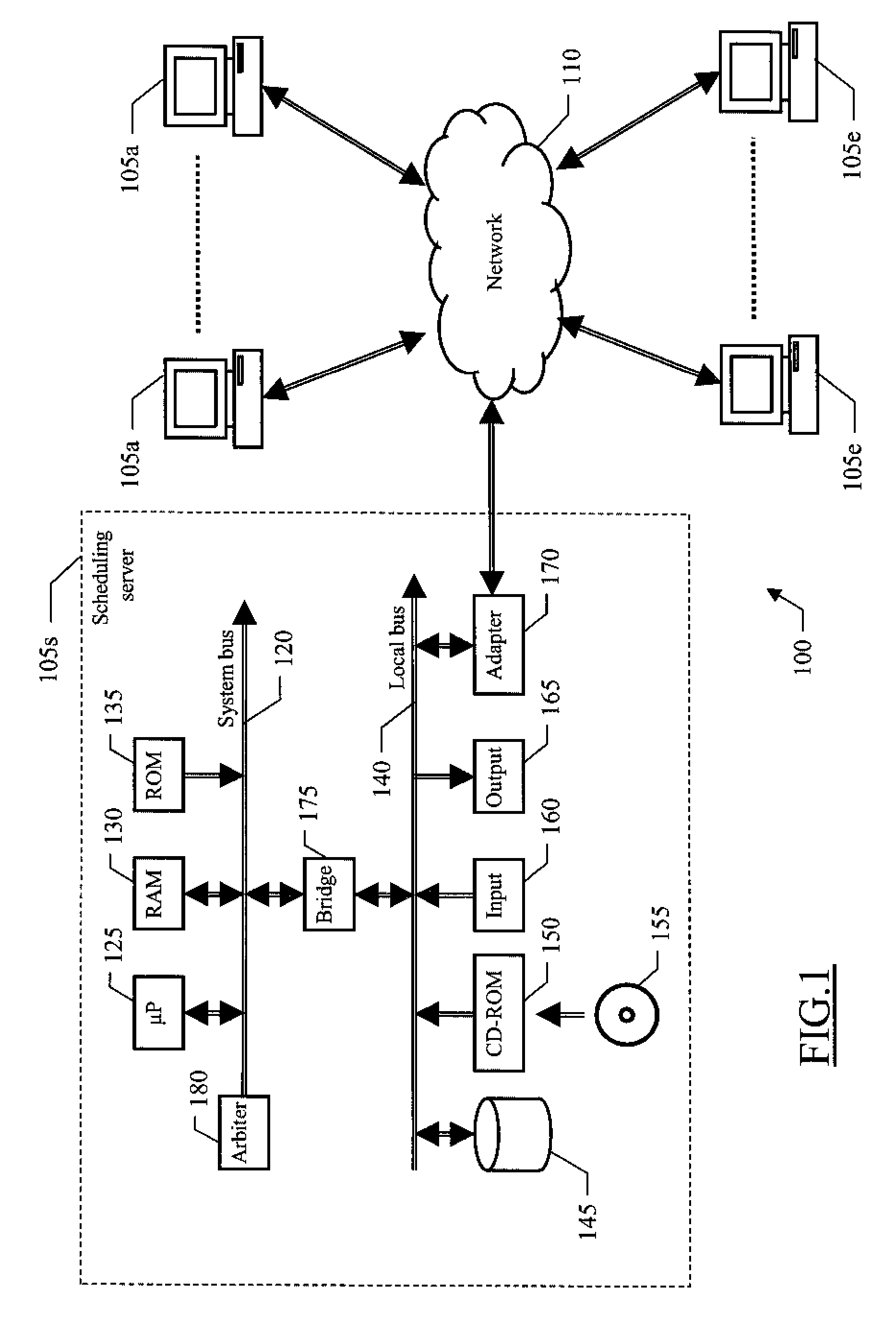
[0029]With reference in particular to FIG. 1, a data processing system 100 with distributed architecture is illustrated. The system 100 includes a plurality of server computers (or simply servers).

[0030]More specifically, one of the servers operates as a scheduling server (denoted with 105s). The scheduling server 105s is used to automate, monitor and control the execution of work units from a central point of the system 100; typically, the work units consist of non-interactive jobs (for example, payroll programs, cost analysis applications, and the like). The jobs are executed on a set of servers operating as execution servers (denoted with 105e). The other servers operate as auxiliary servers (denoted with 105a), which implement additional services that may be used by the execution servers 105s; for example, the auxiliary servers 105s are database servers (controlling one or more databases), application servers (running one or more software applications), and the like.

[0031]The se...


PUM


Abstract

A solution is proposed for facilitating the selection of execution servers to be used in a scheduler for submitting the execution of jobs. Each job is defined by a corresponding descriptor. The descriptor specifies the execution servers to be used by the jobs in a formal way (through their properties); in addition, the descriptor may also include the definition of formal relationships to be satisfied by the execution server with other resources of the system (in turn defined in a formal way through their properties). A query is created according to the descriptor for selecting (concrete) execution servers having the desired properties and satisfying the desired relationships with the resources of the system. This query is then run on a central database, wherein all the concrete execution servers, resources and relationships are defined. In this way, it is possible to obtain a list of concrete execution servers eligible to execute the job in a single transaction.

Description

FIELD OF THE INVENTION[0001]The present invention relates to the information technology field. More specifically, the invention relates to the scheduling of work units in a data processing system.BACKGROUND ART[0002]Scheduling of different work units (for example, batch jobs) is a commonplace activity in data processing systems. For this purpose, workload schedulers are available to automate the submission of large quantities of jobs according to a specific plan (for example, based on constraints defined by the completion of other jobs); an example of commercial scheduler is the “IBM Tivoli Workload Scheduler (TWS)” by IBM Corporation“.[0003]Typically, the scheduler controls the submission of the jobs on a set of execution servers from a central scheduling server. This allows implementing systems to be very powerful and easily scaleable. Moreover, the same structure ensures high reliability (since the plan can be run even in case of failure of one or more execution servers). Workloa...

Claims


Application Information

Patent Timeline
Patent Type & Authority Patents(United States)
IPC IPC(8): G06F9/46G06F7/00G06F15/173
CPCG06F9/4843
Inventor BENEDETTI, FABIODEIDDA, PAOLO
Owner INT BUSINESS MASCH CORP
Why Eureka
Try Eureka