Gear drive

a gear drive and gear face technology, applied in the field of gear drives, can solve the problems of low degree of tooth contact tightness, low structural flexibility of the tooth face profile, and involute gear drives, and achieve the effect of improving the structural flexibility and contact tightness of the gear drive teeth and improving their qualities

Inactive Publication Date: 2011-11-22
NOVIKOV ROMAN VASILYEVICH
View PDF16 Cites 17 Cited by
  • Summary
  • Abstract
  • Description
  • Claims
  • Application Information

AI Technical Summary

Benefits of technology

[0017]It is therefore desirable to increase the structural flexibility and contact tightness of the gear drive teeth in order to improve their qualities. The present invention solves this problem by means of introducing series of kinematical principles that are most suitable for employment of the contact curvature effect during various engagement phases.

Problems solved by technology

The involute gear drive has some disadvantages, such as low structural flexibility of the tooth face profile (danger of edge engagement phase and presence of pole engagement phase, low degree of tooth contact tightness) and high sensitivity to process and deformation irregularities of the tooth contact along a line of teeth.
), and satisfies the basic law of meshing by means of axially intermating teeth with addendum mating (εα=0) of their face profiles, convex of radius ρα at a tooth addendum and concave of radius ρf at a tooth dedendum, Δρ=ρf−ρα>0. The Novikov gear drive has disadvantages such as low structural flexibility—lacking a principle ability to design a spur gear and / or narrow-crown drive, necessity to choose the value of Δρ>>0, low degree of tooth contact tightness, and its increased sensitivity to process and deformation irregularities of shape.
The known gear drive has certain disadvantages such as limited structural flexibility regarding an increase of contact tightness (and employment of the curvature effect) during phases of extra-pole meshing, as well as in selecting parameters of longitudinal (εβ≧1) tooth shape.
The disadvantages of this solution are limitations of structural flexibility regarding employment of the curvature effect and increase of contact tightness during all engagement phases.
At the same time, the complying with condition εα≧1 imposes limitations on the structural flexibility of the multi-flow IP drive regarding employment of effects of curvature and contact tightness increase.

Method used


Image

  • Gear drive
  • Gear drive
  • Gear drive

Examples


Embodiment Construction

[0053]While the invention may be susceptible to embodiment in different forms, there are shown in the drawings, and will be described in detail herein, specific embodiments of the present invention, with the understanding that the present disclosure is to be considered an exemplification of the principles of the invention, and is not intended to limit the invention to that as illustrated and described herein.

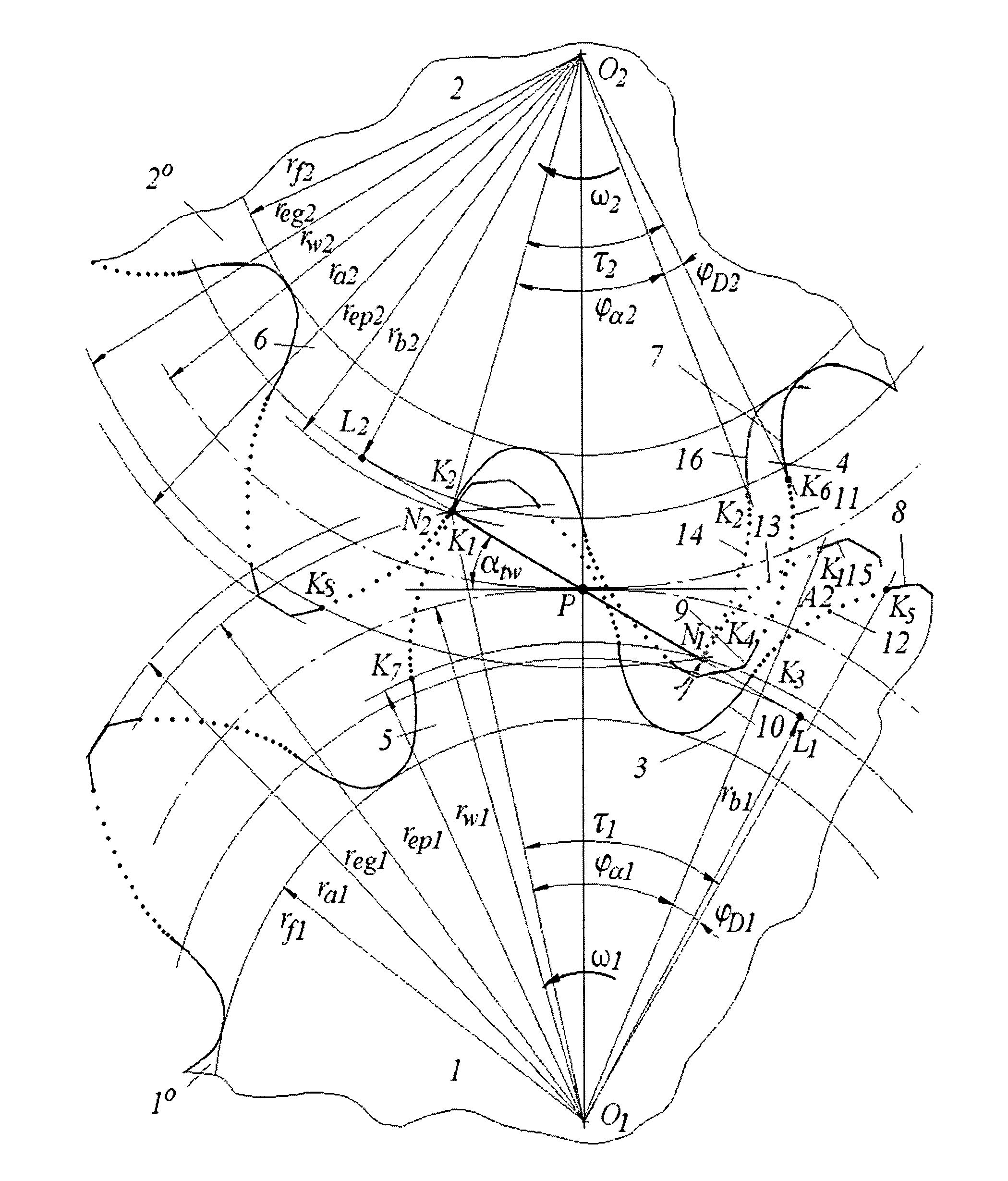
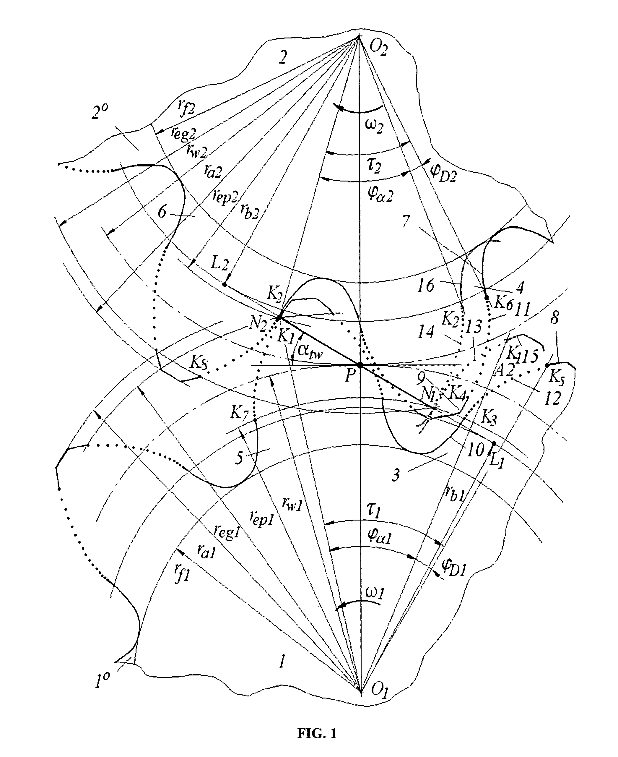
[0054]A cylindrical gear (shown on FIG. 1) is designed according to the invention, and can be used in a heavy-duty drive, formed by toothed wheels (1) and (2) (with axles O1,2 and circles: pitch, top and dedendum, of radii rw1,2, rα1,2 and rf1,2, respectively) that rotate with angular speeds ω1 and ω2. Hereinafter parameters marked by subscripts 1 and 2 refer to the paired wheels 1 and 2, respectively.

[0055]Side surfaces of face profiles of interacting teeth (3)-(4) and (5)-(6) on the toothed crowns 1° and 2° comprise pointwise conjugate extra-pole arc-shaped (convex of radius ρ...


PUM


Abstract

The inventive gear drive comprises toothed wheels with teeth of toothed crowns interacting with single- or multi-flow elements. Working profiles of the interacting teeth comprise piecewise and / or pointwise conjugate, convex at a tooth point and concave at a tooth root arc-shaped sections continuously connectable to each other or to involute sections. The interacting toothed crowns are so embodied that a phase gap of the face tooth intermating at a discrete angle from a point, where the interaction of profiles ends at a point, where the interaction of the face profiles of the next tooth pair starts. The drive is so embodied that the face tooth overlap ratio thereof is less than 1. The so improved teeth provide for high level of the contact tightness and absence of axial forces at engagement, increase the structural flexibility of the gear drive teeth in order to improve their qualities.

Description

CROSS-REFERENCE TO RELATED APPLICATIONS[0001]This application is a U.S. national phase application of a PCT application PCT / RU2005 / 000367 filed on 5 Jul. 2005, published as WO2007 / 008096, whose disclosure is incorporated herein in its entirety by reference.FIELD OF THE INVENTION[0002]The invention relates to machinery, specifically to gear drives. The most successful possible use of this invention is proposed for various devices with heavy loaded toothed wheels.BACKGROUND OF THE INVENTION[0003]Involute (or evolvent) gear drives are known (F. L. Litvin “Teoriya zubchatykh zatsepleniy”, Moscow, Nauka, 1968, 584 pp.), that comply with the basic law of meshing by means of intermating tooth face profiles of paired wheels, with the following overlap ratio (εα) and total overlap ratio (εγ): εα≧1 and εγ≧1. The involute gear drive has some disadvantages, such as low structural flexibility of the tooth face profile (danger of edge engagement phase and presence of pole engagement phase, low de...

Claims


Application Information

Patent Timeline
Patent Type & Authority Patents(United States)
IPC IPC(8): F16H55/00F16H55/08
CPCF16H55/08Y10T74/19949Y10T74/19972
Inventor ZHURAVLEV, GERMAN ALEXANDROVICH
Owner NOVIKOV ROMAN VASILYEVICH
Why Eureka
Try Eureka