Interchangable chipper inserts for wood grinder

a wood grinder and insert technology, applied in the field of wood reduction machines, can solve the problems of not all wood waste is suitable for the production of wood chips, the equipment for wood reduction is rather expensive, and many wood waste processors may not be able to afford both wood grinders and wood chippers, etc., to achieve the effect of simple and effective structure, limited labor and cost, and easy fitting

Active Publication Date: 2011-11-22
ALAMO GROUP
View PDF26 Cites 14 Cited by
  • Summary
  • Abstract
  • Description
  • Claims
  • Application Information

AI Technical Summary

Benefits of technology

In one embodiment, the cutters are double-edged blades that are removable secured in the cutter pockets. The cutters may be reversed when one edge becomes dull. The chipper inserts may include a cutter block supported within the cutter pocket. The cutters may be secured to the cutter blocks by bolts or other fasteners that facilitate quick and easy reversing or replacement of the cutters. The cutters protrude from the pockets a desired distance. This distance may vary from application to application depending in part on the desired chip size and the spacing between the chipper drum and the anvil or grinding grates.
The present invention provides a simple and effective structure to permit a single wood reduction apparatus to selectively function as either a chipper or a grinder. The chipper inserts can be easily fitted onto an existing hammermill without the need to customize the rotor. For example, the chipper inserts may be designed for installation using the rotor pins of a conventional stacked-plate rotor. Accordingly, many types of pre-existing wood grinders can be converted into a wood grinder without any type of modification to the underlying rotor structure. This allows conversion with relatively limited labor and cost. Because the chipper inserts define a generally continuous drum, they facilitate consistent chip size and generally eliminate dead spaces. This translates to improved operation and improved output quality. The use of left and right cutter inserts allows the cutters to be positioned closer to the left and right ends of the chipper drum to reduce dead end spaces. Because the chipper inserts may be designed in quadrant sections and may be shorter in axial length than the rotor, the individual chipper inserts may be relatively easy to handle manually, which facilitates removal installation.

Problems solved by technology

However, not all wood waste is suitable for the production of wood chips.
Wood reduction equipment can be rather expensive, and many wood waste processors may not be able to afford both wood grinders and wood chippers.
Although lower quality wood waste may be used as a fuel source, ground wood waste can present problems for wood fuel handling systems.
Many conventional pneumatic feed systems do not work as well with ground wood waste, presumably because it has a greater tendency than wood chips to cling or clump together.
However, the cost of adding a wood chipper to permit occasion use may be cost prohibitive.
In fact, significant portions of the rotor plates are exposed to the wood waste during wood reduction.
Although the knife inserts allow the wood grinder to be converted into a chipper, the system has inherent limitations that may affect chip quality and may lead to inconsistent chip size.
For example, because of the open spaces between and around the knives, the chipper mill has relatively large dead spaces and provides relatively little control over chip size and chip quality.

Method used


Image

  • Interchangable chipper inserts for wood grinder
  • Interchangable chipper inserts for wood grinder
  • Interchangable chipper inserts for wood grinder

Examples


Embodiment Construction

I. Overview

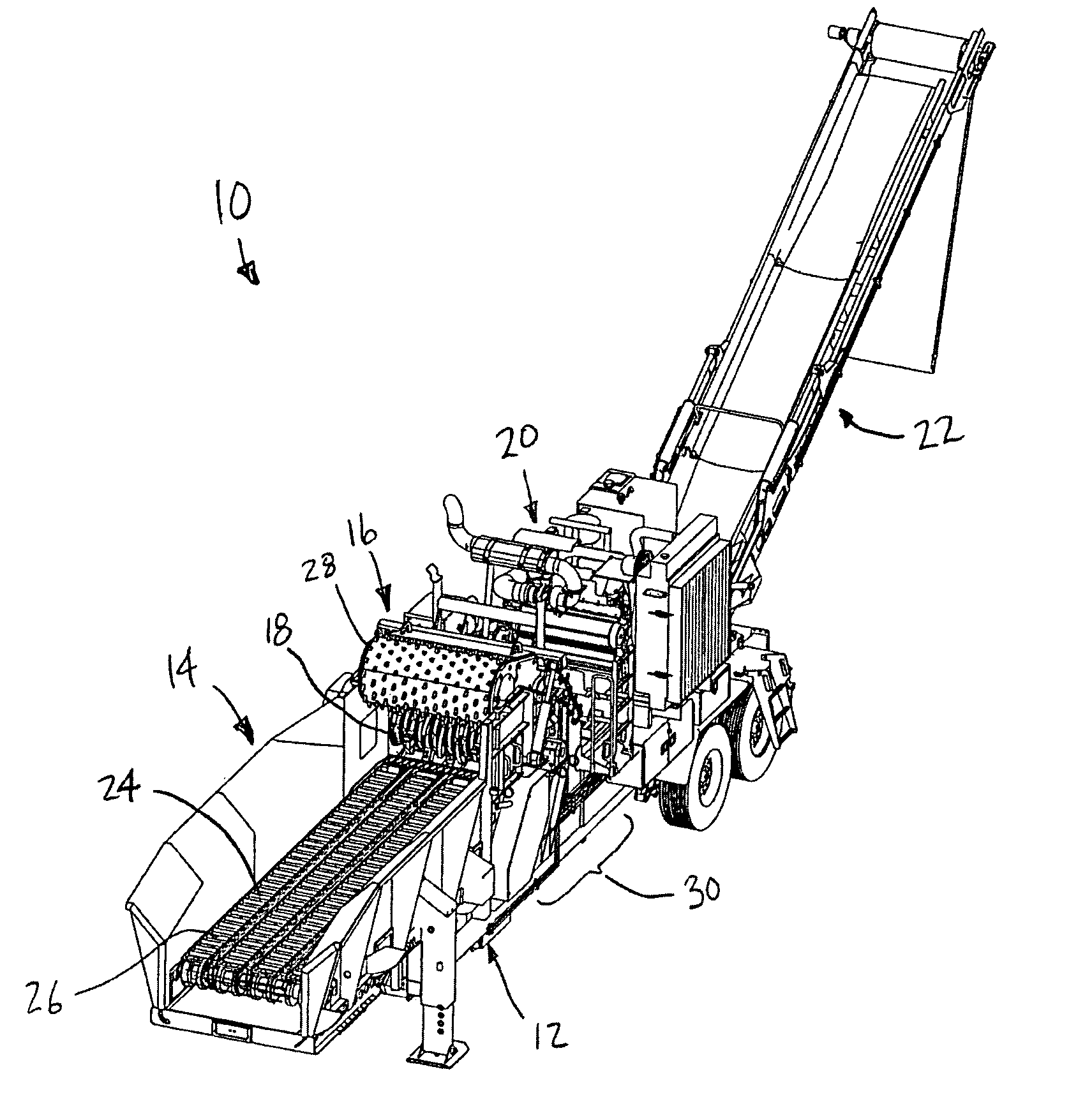
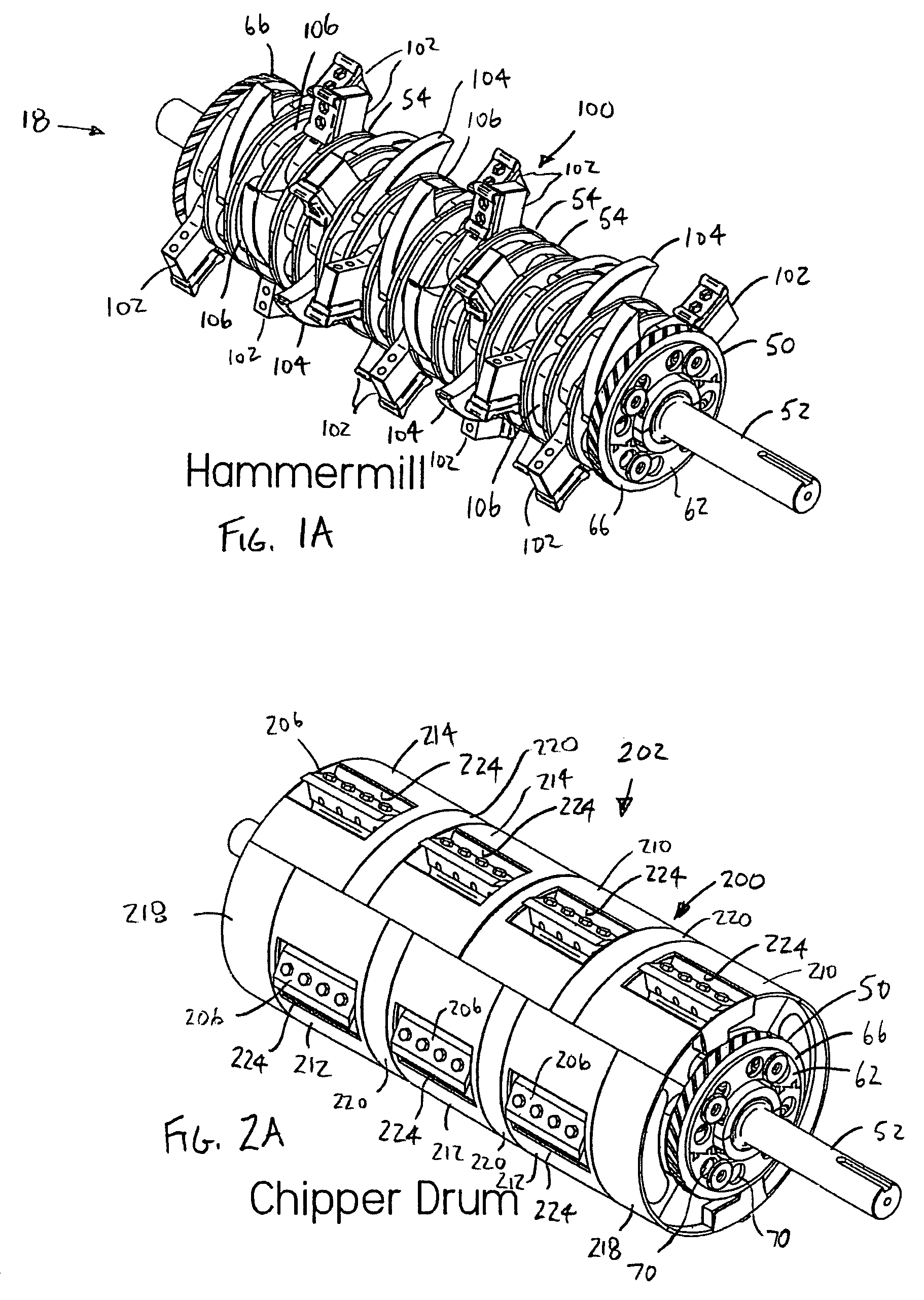
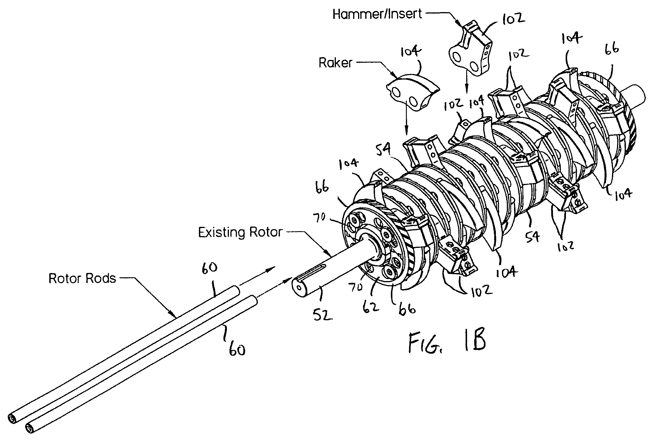
The present invention is directed to chipper inserts that permit a hammermill rotor (See FIGS. 1A and 1B) to selectively function as a chipper. The chipper inserts may be fitted onto a rotor in place of the hammer inserts to provide a chipper drum (See FIGS. 2A and 2B). For purposes of disclosure, the present invention is described in connection with illustrations of a specific wood reduction apparatus having a “stacked-plate” rotor (See FIG. 3). The present invention is not limited, however, to use with stacked-plate rotor, but instead is suitable for use with essentially any rotor capable of receiving interchangeable chipper inserts.

In the illustrated embodiment, the rotor 50 generally includes a shaft 52 carrying a plurality of stacked rotor plates 54 and spacers 56 (See FIGS. 3A and 3B). The rotor plates 54 have a substantially greater diameter that the spacers 56. The rotor plates 54 and spacers 56 alternate along the shaft 52 to provide a plurality of annular slots ...


PUM

PropertyMeasurementUnit
angleaaaaaaaaaa
angleaaaaaaaaaa
angleaaaaaaaaaa

Abstract

A plurality of chipper inserts that may be installed on a hammermill rotor in place of the hammer inserts to selectively convert the rotor to a chipper. The chipper inserts include drum surfaces that cooperatively define a chipper drum. The chipper inserts may include cutter inserts that have a cutter disposed in a cutter pocket. The chipper drum may be a generally continuous cylindrical interrupted essentially only by the cutter pockets. The cutters and cutter pockets may be positioned in essentially any desired pattern around the drum. The chipper inserts may include a left cutter insert, a center cutter insert, a right cutter insert and three different size spacer inserts. The different types of cutter inserts and spacer inserts may be installed about the rotor with at least one left cutter insert mounted on the left end of the chipper drum and at least one right cutter insert mounted on the right end of the chipper drum. The chipper inserts may be configured in quadrant sections, such that it takes four inserts to extend around the rotor.

Description

BACKGROUND OF THE INVENTIONThe present invention relates to equipment for reducing wood and more particularly to wood reduction machines for chipping or grinding scrap timber, limbs, brush and other wood waste.There is a wide variety of machines available on the market for reducing waste wood, such as scrap timber, tree limbs and brush. The two most common types of wood reduction machines are chippers and grinders. As the names imply, chippers reduce wood by cutting it into wood chips using a set of chipper knives and grinders operate by essentially hammering wood into wood fragments using a hammermill.The type of wood reduction equipment used in a given situation is often dictated by the character of the wood waste. On the market, wood chips typically bring a premium over ground wood. However, not all wood waste is suitable for the production of wood chips. With lower quality wood waste that may include a substantial amount of sand, gravel and other contaminants, it may be desirabl...

Claims


Application Information

Patent Timeline
Patent Type & Authority Patents(United States)
IPC IPC(8): A47J43/25
CPCB02C13/06B02C13/2804B02C18/145B02C18/18
Inventor COTTER, CHAD J.LANGWORTHY, NELSON C.
Owner ALAMO GROUP
Why Eureka
Try Eureka