

Mortarless modular precast cladding system
a modular, concrete technology, applied in the direction of sustainable buildings, walls, light and heating equipment, etc., can solve the problems of lack of airspace for ventilation between the cladding and the structure, the lack of engineered drainage galleries or rainscreens, and the labor and material intensive full masonry application, etc., to achieve maximum resilience to deformation, simple, rapid and uniform installation
- Summary
- Abstract
- Description
- Claims
- Application Information
AI Technical Summary
Benefits of technology
Problems solved by technology
Method used
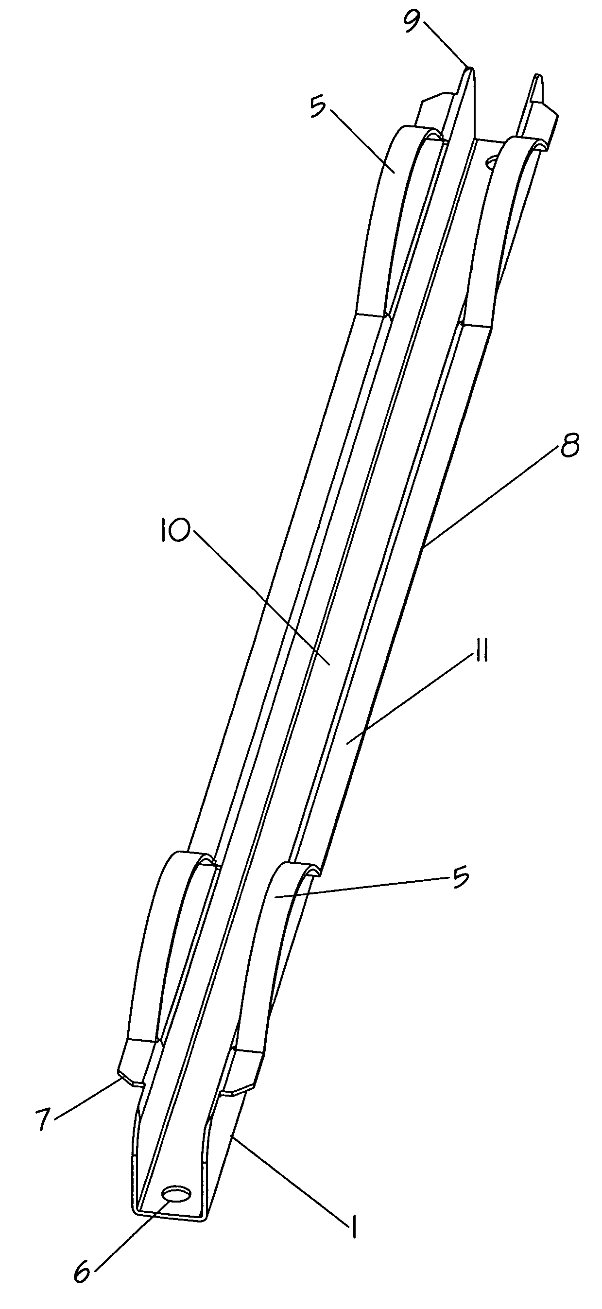
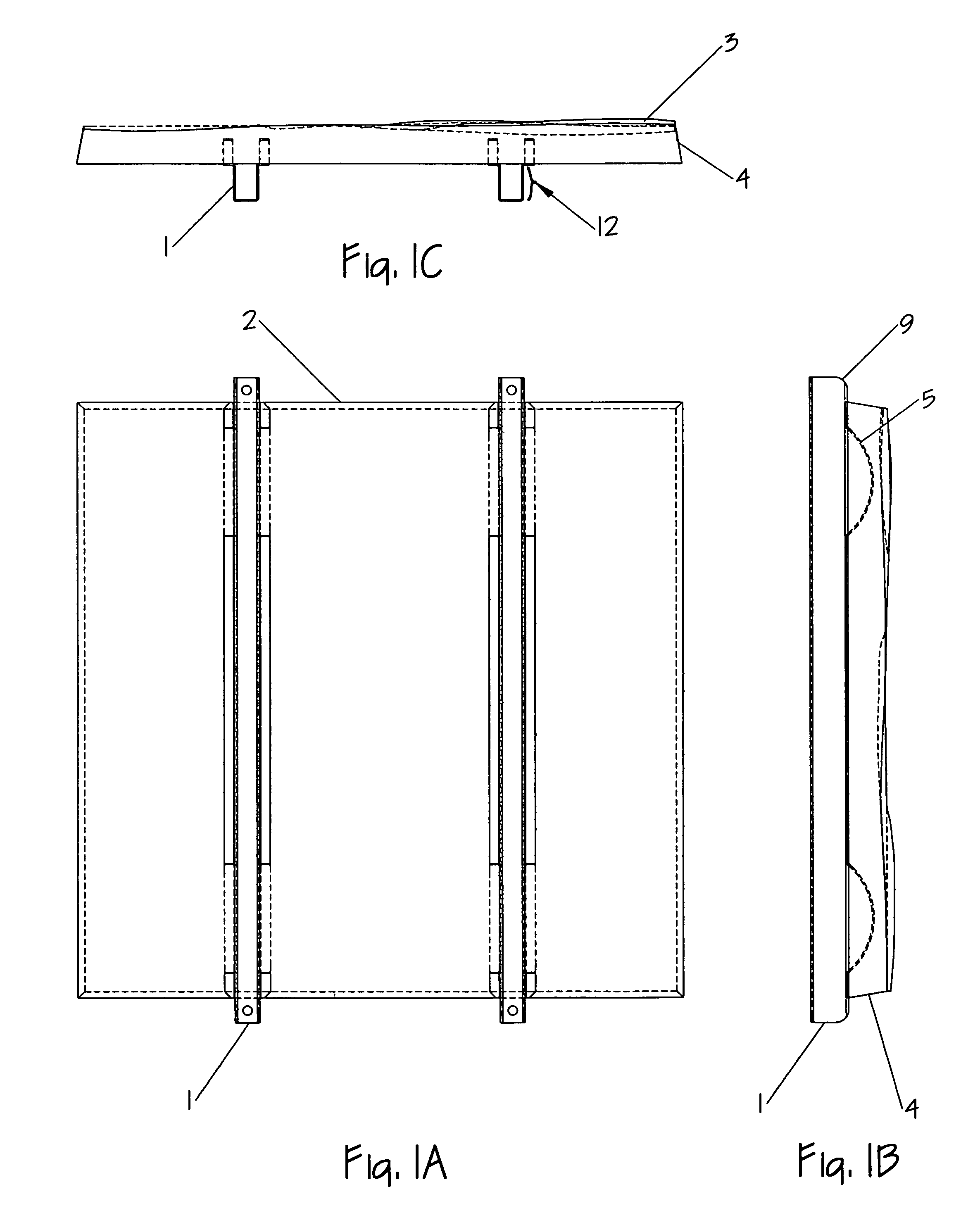
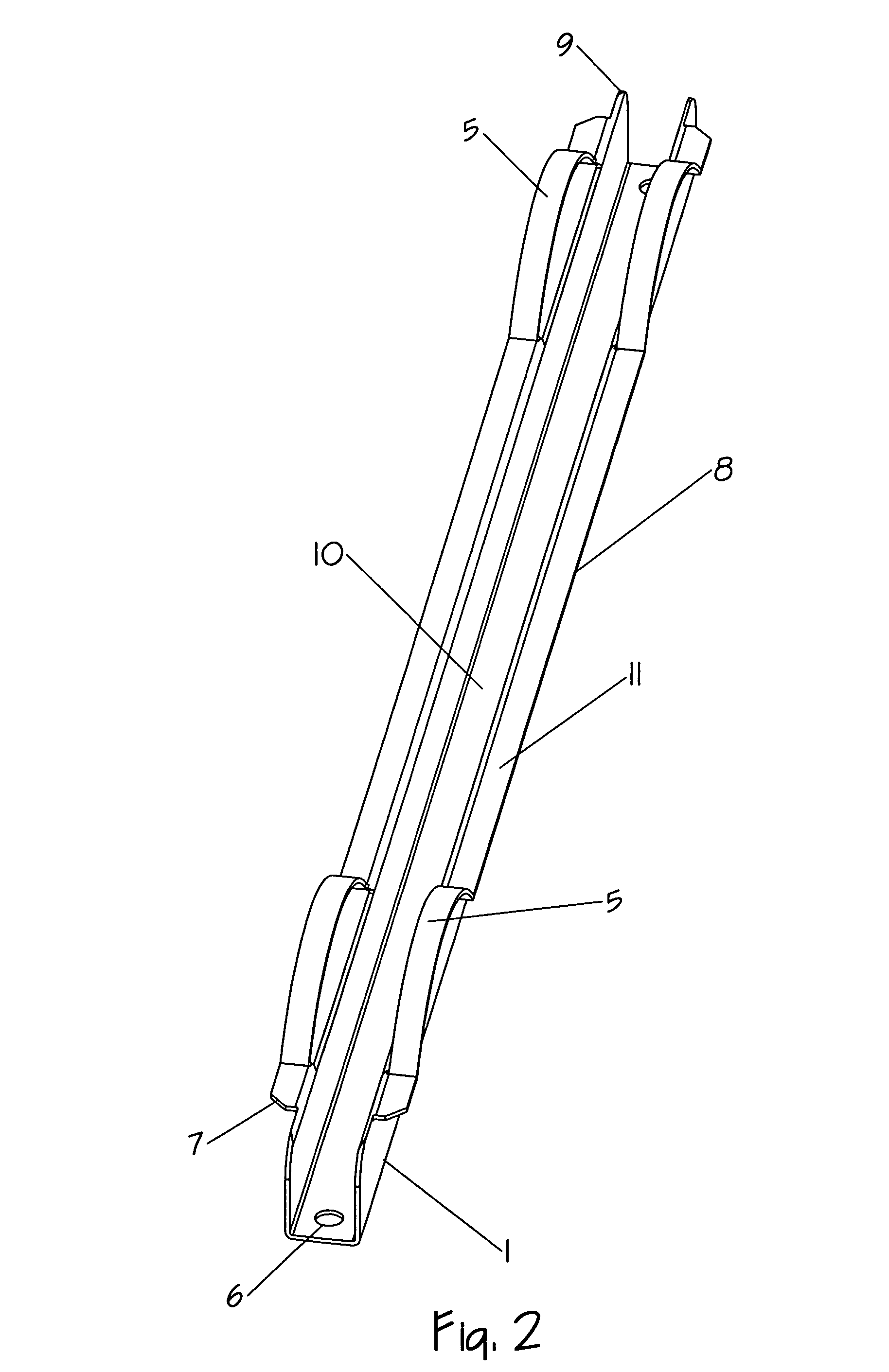
Image

Examples
Embodiment Construction
[0035]The following discussion is directed to various embodiments of the invention. Although one or more of these embodiments may be preferred, the embodiments disclosed should not be interpreted, or otherwise used, as limiting the scope of the disclosure, including the claims. In addition, one skilled in the art will understand that the following description has broad application, and the discussion of any embodiment is meant only to be exemplary of that embodiment, and not intended to intimate that the scope of the disclosure, including the claims, is limited to that embodiment.
[0036]Accordingly, several objects and advantages of my invention are:
[0037](a) to provide both an improved and alternate mortarless mechanical connection design that offers the manufacturer the option of either cast-in-place channel connectors embedded at point of manufacture, or producing the precast cladding units without the connectors in place, and anchored after manufacture on the jobsite.
[0038](b) to...
PUM
| Property | Measurement | Unit |
|---|---|---|
| volume | aaaaa | aaaaa |
| weight | aaaaa | aaaaa |
| strength | aaaaa | aaaaa |
Abstract
Description
Claims
Application Information