
Metal laminate gasket

a technology of metal laminate and gasket, which is applied in the direction of engine seals, embroidering machines, textiles and paper, etc., can solve the problems of mechanical strength declining, maximum explosion pressure rising, and maximum explosion pressure rising

Inactive Publication Date: 2006-07-27
ISHIKAWA GASKET CO LTD
View PDF14 Cites 10 Cited by
  • Summary
  • Abstract
  • Description
  • Claims
  • Application Information

AI Technical Summary

Benefits of technology

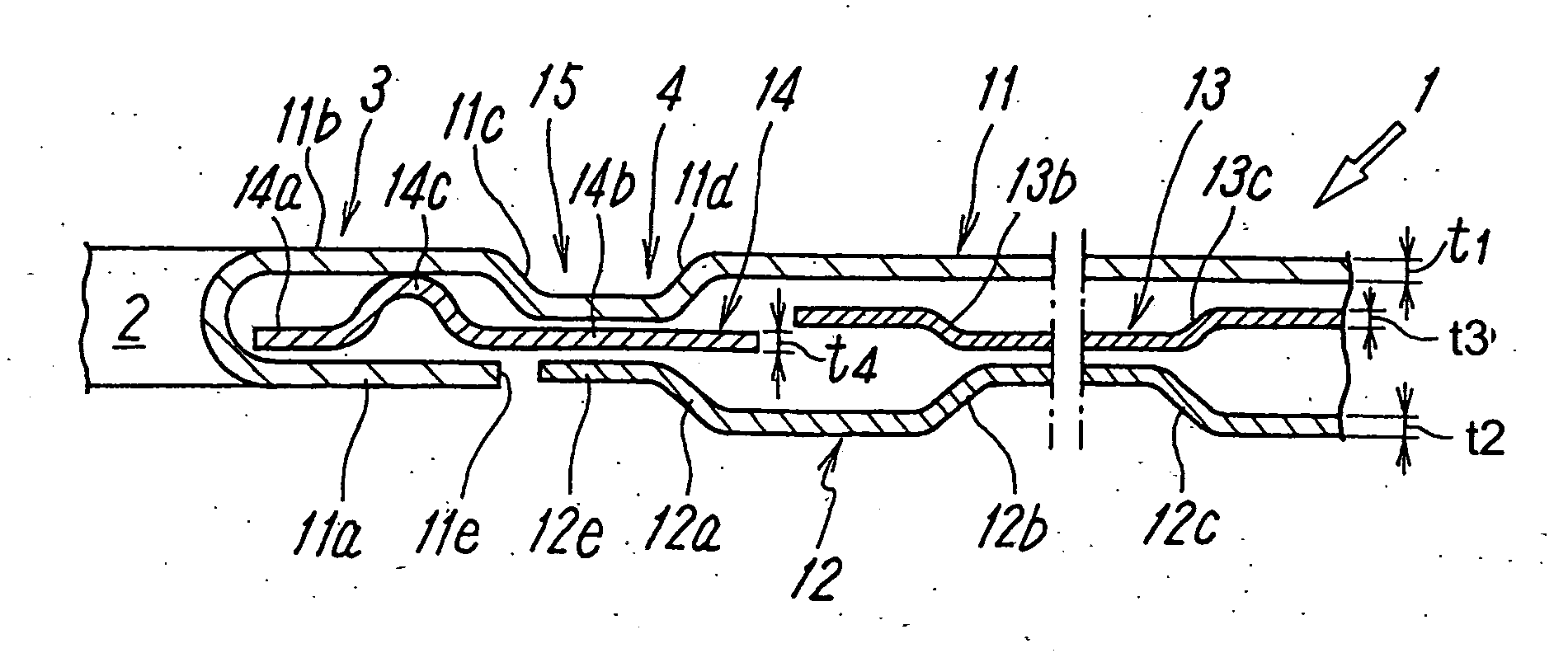
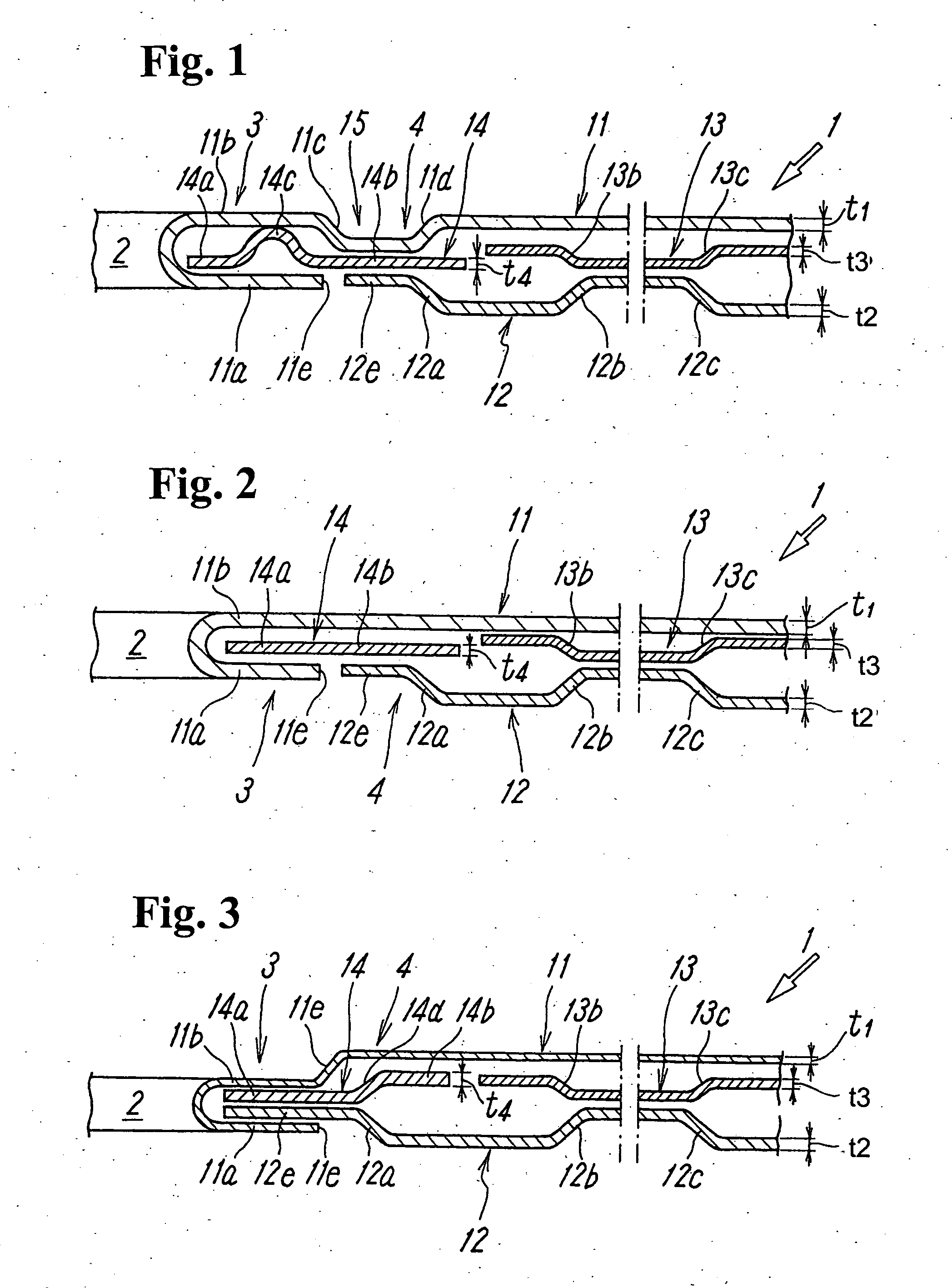
[0013] In the metal laminate gasket with the above-described structure, the primary sealing portion is formed by the folded place of the first metal plate sandwiching the sandwiched member, and the secondary sealing portion is formed by the first and second metal plates in the place wherein the extension portion of the bore ring is sandwiched. As a result, the secondary sealing portion differs from a secondary sealing portion consisting of heat-resisting rubber, and includes excellent heat resistance as in the case with a primary sealing portion consisting of the metal plate.
[0016] In addition, the total thickness of the first and second metal plates and the bore ring in the secondary sealing portion is made smaller than the total thickness of the double thickness of the first metal plate in the primary sealing portion; and the thickness of the sandwiched member. As a result, the elastic resilience of the secondary sealing portion is larger than the elastic resilience of the primary sealing portion so that the secondary sealing portion includes an excellent following capability relative to the lift compared to the primary sealing portion.
[0018] As a result, the load balance relative to the primary sealing portion, secondary sealing portion, and the sealing portions around the various types of holes whose circumferences should be sealed in the metal laminate gasket can be appropriately distributed.
[0019] According to the metal laminate gasket of the present invention described above, a metal laminate gasket is provided whose following capability for the lift of the cylinder head is improved. More specifically, the metal laminate gasket can ensure the following capability by the secondary sealing portion with heat resistance when the cylinder head is widely lifted. At the same time, the load balance relative to the primary sealing portion, secondary sealing portion, and the sealing portions around the various types of holes whose circumferences should be sealed can be appropriately distributed.

Problems solved by technology

Recently, with the high performance of an engine, maximum explosion pressure has a tendency to rise.
Especially, in a diesel engine, the maximum explosion pressure has a significant tendency to rise.
On the other hand, with the reduction in weight of the engine, the mechanical strength has a tendency to decline.
However, for example, in a conventional metal laminate cylinder head gasket wherein a primary sealing portion including a sealing bead around a combustion-chamber hole is formed, the amount of compression of the sealing bead is essentially not large compared to the lift.
As a result, the following capability for the lift whose size just grew larger cannot be ensured so that an additional following capability is required.

Method used


Image

  • Metal laminate gasket
  • Metal laminate gasket

Examples


first embodiment

[0023]FIG. 1 shows a cross-sectional shape of the circumference of a combustion-chamber hole 2 in a metal laminate gasket according to the present invention. A metal laminate gasket 1 is formed by laminating the first, second, and third metal plates 11, 12, 13 in whole, and includes the combustion-chamber hole 2 corresponding to a combustion chamber of a cylinder block and a hole (not shown in the figure) corresponding to a fluid hole whose circumference should be sealed.

[0024] Also, in the rim of the combustion-chamber hole 2 of the metal laminate gasket 1, the first metal plate 11 constituting one side of an outer plate of the gasket is folded back, and a sandwich portion 14a of a bore ring 14 consisting of a ring-shaped metal plate is sandwiched in a folded portion 11a. At the same time, the second metal plate 12 constituting another outer plate is laminated on the face of the folded side of the first metal plate 11, and an extension portion 14b of the bore ring 14 projecting out...

third embodiment

[0046] In the third embodiment, the sealing bead 11e whose height is higher than the metal-plate portion 11b of the folded place of the first metal plate 11 is provided even in the first metal plate 11 in the place where the extension portion 14b is sandwiched, in addition to the sealing bead 12a provided in the metal plate 12. Moreover, the circular sealing bead 14d is formed in the extension portion 14b of the bore ring 14, is concentric with the half bead 12a of the second metal plate 12, and slopes in the opposite direction of the half bead 12a from the same radial position with the half bead 12a. As a result, the following capability relative to the lift of the cylinder head is additionally improved.

[0047] Also, in the third embodiment, the sandwich portion 14a of the bore ring 14 and the hole-rim portion 12e of the second metal plate 12 are sandwiched by: the folded portion 11a in the folded place of the first metal plate 11; and the metal-plate portion 11b. As a result, the b...


PUM


Abstract

A metal gasket for an internal combustion engine includes a first metal plate with a folded portion; a ring member with a sandwiched portion having a sealing bead and an extension portion, with the sandwiched portion being sandwiched in the folded portion to provide a primary sealing portion; a second metal plate laminated to the folded portion of the first metal plate so as to sandwich the extension portion to provide a secondary sealing portion; and a third metal plate sandwiched between the first metal plate and the second metal plate in a portion of the gasket separate from the sandwiched extension portion. In the event that the cylinder head lift becomes greater than the following capability of the sealing bead in the primary sealing portion, the secondary sealing portion provides excellent following capability relative to the lift.

Description

BACKGROUND OF THE INVENTION AND RELATED ART STATEMENT [0001] The present invention relates to a metal laminate gasket to be installed between a cylinder head and the cylinder block of an internal combustion engine, to seal therebetween. More specifically, the present invention relates to a metal laminate gasket whose secondary sealing portion is reinforced. [0002] Recently, with the high performance of an engine, maximum explosion pressure has a tendency to rise. Especially, in a diesel engine, the maximum explosion pressure has a significant tendency to rise. On the other hand, with the reduction in weight of the engine, the mechanical strength has a tendency to decline. As a result, at the time of the explosion inside the cylinder, the lift of a cylinder head becomes large, and the following capability of a cylinder head gasket for the lift is required. [0003] However, for example, in a conventional metal laminate cylinder head gasket wherein a primary sealing portion including a ...

Claims


Application Information

Patent Timeline
Patent Type & Authority Applications(United States)
IPC IPC(8): F02F11/00
CPCF02F11/002F16J15/0825F16J2015/0837F16J2015/0862D05C1/08D05C17/00
Inventor KASUYA, TADASHI
Owner ISHIKAWA GASKET CO LTD
Learn More